Showing posts with label Oklahoma. Show all posts
Showing posts with label Oklahoma. Show all posts
Mead O'Brien: Problem Solver, Innovator, and Best Total Cost Provider
Mead O’Brien specializes in valves & valve automation, steam & hot water products and systems, instrumentation products, skid designs, field services, surveys, assessments, and consulting. The extensive product and application knowledge possessed by the Mead O'Brien sales force projects to all or part of ten states in the Midwest which includes Missouri, Kansas, Nebraska, Iowa, Oklahoma, Arkansas, Texas Panhandle, Southern Illinois, Western Kentucky, and Southwest Indiana.
How Your Steam Trap Selection Affects Your Bottom Line Profits: Inverted Bucket Trap vs.Thermodynamic Trap

The ability to monitor and maintain your facility’s steam trap population directly affects your bottom line. Armstrong’s Steam Testing and Monitoring Systems give you the means to achieve best practice steam system management by proactively monitoring your steam trap inventory.
For more information on Armstrong steam and hot water products, visit Mead O'Brien at https://meadobrien.com of call (800) 892-2769.
Expert Valve Automation and Valve Communications Services
With expertise in pneumatic rack and pinion and scotch-yoke, as well as electric quarter-turn and linear, Mead O'Brien has the experience and facilities to deliver a well engineered automated valve package.
Call (800) 892-2769 or visit https://meadobrien.com for more information on any valve automation requirement.
Call (800) 892-2769 or visit https://meadobrien.com for more information on any valve automation requirement.
Process Instrumentation and Noise
 |
| Protect process instrumentation from electrical noise. |
No matter the cause for the process noise, the measurement signal in the process is being distorted and is not reflecting the true state of the process at a certain time. Accuracy and precision of process measurements are negatively affected by noise, and can also contribute to errors in control system. Controller output can reflect the noise affecting a process variable.
Grounding allows for the reduction of noise stemming from electrical systems. Shielded cabling and separating signal cabling from other wiring, as well as replacing and repairing sensors, allows for noise reduction. Low-pass filters are a way to compensate for noise, and much of the instrumentation used in process systems incorporates noise dampening features automatically. Determining the best kind of filter to use depends heavily on cut-off frequency, alpha value, or time constant.
The ideal low-pass filter would eliminate all frequencies above the cutoff frequency while allowing every frequency below the cut-off frequency to be unaffected. However, this ideal filter is only achievable mathematically, while real applications must approximate the ideal filter. They calculate a finite impulse response, and also must delay the signal for a bit of time. To achieve better filter accuracy, a longer delay is needed so that the filter computation “sees” a bit further into the future. The calibration of these filters heavily relies on the desired accuracy level of the process, while also taking specific steps in calibration to best fit a particular process.
Noise is important to mitigate because the noise observed while measuring the process variable can produce “chatter” in the final control element of a process. The resulting “chatter” increases the wear of mechanical control elements, such as valves, and will generate additional cost for the process as a whole. The filtered signal lagging behind the dynamic response of the unfiltered signal is a result of the filtered signal’s increased dead time, meaning that signal filters add a delay in sensing the true process state. The solution is to find a mid-point between signal smoothing and information delay, which allows for elimination of noise while not negatively affecting the speed by which information is delivered.
For question about any process control application, or challenge, visit https://meadobrien.com or call (800) 892-2769
What Are Isolation Rings?
 |
| Isolation Rings (Ashcroft) |
The ring design includes ring has a flexible inner cylinder that prevents process media from collecting in the instrument, and therefore assuring reliable and continuous pressure measurement. An integrated needle valve allows for fast and easy removal for instrument repair, replacement, or calibration without interrupting the process media flow. The needle valve can also be used for pulsation dampening.
Watch the video below for a more in-depth understanding of how Isolation Rings are installed and operate.
For more information, contact Mead O'Brien by calling (800) 892-2769 or visiting https://meadobrien.com.
Commissioning a Glass Level Gauge with a Safety Ballcheck Valve
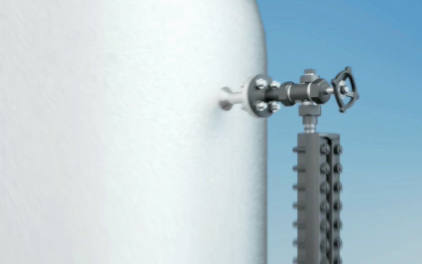
https://meadobrien.com
(800) 892-2769
Steam Trapping and Steam Tracing Equipment
 |
| Inverted Bucket Steam Trap (Armstrong) |
As a steam trap wears, it loses efficiency and begins to waste energy. But Armstrong inverted bucket traps last years longer than other traps. They operate more efficiently longer because the inverted bucket is the most reliable steam trap operating principle known.
Clearly, the longer an efficient trap lasts, the more it reduces energy wasted, fuel burned and pollutants released into the air. It’s an all-around positive situation that lets the environment win, too. Bringing energy down to earth in your facility could begin with a renewed focus on your steam system, especially your steam traps. Said another way: Zeroing in your steam traps is an easy way to pay less money for energy—and more attention to the environment.
Companies around the world are beginning to realize that rather than being separate challenges, energy and the environment are and have always been a single mission. And that quality management in one area will surely impact the other.
The catalog below should be utilized as a guide for the installation and operation of steam trapping equipment. Selection or installation should always be accompanied by competent technical assistance or advice. Armstrong and its local representatives are available for consultation and technical assistance. We encourage you to contact your Armstrong Representative for complete details.
The Orifice Plate: Great for Gases, Clean Liquids, and Low Velocity Steam
 |
| Orifice plate mounted in flange and alone. Courtesy of Armstrong International. |
Orifice plates are the most commonly used differential pressure measurement device and are applicable for measurements in gases, clean liquids, and low velocity steam. Orifice plates allow for relatively easy installation and replacement if necessitated by changes in process parameters or life cycle deterioration.
An orifice plate is often mounted in a customized holder or flange union that allows removal and inspection of the plate. A holding device also facilitates replacement of a worn orifice plate or insertion of one with a different size orifice to accommodate a change in the process. While the device appears simple, much care is applied to the design and manufacture of orifice plates. The flow data obtained using an orifice plate and differential pressure depend upon well recognized characteristics of the machined opening, plate thickness, and more. With the pressure drop characteristics of the orifice fixed and known, the measuring precision for differential pressure becomes a determining factor in the accuracy of the flow measurement.
 |
| Orifice plate configurations (click for larger view). |
- Circularity of the bore
- Flatness
- Parallelism of the faces
- Edge sharpness
- Surface condition
Certain aspects of the mounting of the orifice plate may also have an impact on its adherence to the calibrated data for the device. Upstream and downstream pipe sections, concentric location of the orifice in the pipe, and location of the pressure measurement taps must be considered.
 |
| Orifice plate between two flanges. |
Download a cut sheet for Armstrong orifice plates and flanges from this Mead O'Brien link.
For more information, call (800) 892-2769 or visit https://meadobrien.com.
Industrial Valve Actuators
Valve actuators are selected based upon a number of factors including torque necessary to operate the valve and the need for automatic actuation. Types of actuators include manual handwheel, manual lever, electrical motor, pneumatic, and solenoid. All actuators except manual handwheel and lever are adaptable to automatic actuation.
Manual Actuators
Manual actuators are capable of placing the valve in any position but do not permit automatic operation. The most common type mechanical actuator is the handwheel. This type includes handwheels fixed to the stem and handwheels connected to the stem through gears.
Electric Motor Actuators
Electric motors permit manual, semi-automatic, and automatic operation of the valve. Motors are used mostly for open-close functions, although they are adaptable to positioning the valve to any point opening. The motor is usually a, reversible, high speed type connected through a gear train to reduce the motor speed and thereby increase the torque at the stem. Direction of motor rotation determines direction of disk motion. The electrical actuation can be semi-automatic, as when the motor is started by a control system. A handwheel, which can be engaged to the gear train, provides for manual operating of the valve. Limit switches are normally provided to stop the motor automatically at full open and full closed valve positions. Limit switches are operated either physically by position of the valve or torsionally by torque of the motor.
Pneumatic Actuators
Pneumatic actuators provide for automatic or semi-automatic valve operation. These actuators translate an air signal into valve stem motion by air pressure acting on a vane, diaphragm, or piston connected to the stem. Pneumatic actuators are used in throttle valves for open-close positioning where fast action is required. When air pressure closes the valve and spring action opens the valve, the actuator is termed direct-acting. When air pressure opens the valve and spring action closes the valve, the actuator is termed reverse-acting. Double acting actuators have air supplied to both sides of the vane, diaphragm, or piston. The differential pressure across the diaphragm positions the valve stem. Automatic operation is provided when the air signals are automatically controlled by circuitry. Semi-automatic operation is provided by manual switches in the circuitry to the air control valves.
Hydraulic Actuators
Hydraulic actuators provide for semi-automatic or automatic positioning of the valve, similar to the pneumatic actuators. These actuators use a piston to convert a signal pressure into valve stem motion. Hydraulic fluid is fed to either side of the piston while the other side is drained or bled. Water or oil is used as the hydraulic fluid. Solenoid valves are typically used for automatic control of the hydraulic fluid to direct either opening or closing of the valve. Manual valves can also be used for controlling the hydraulic fluid; thus providing semi-automatic operation.
Solenoid Actuated Valves
Solenoid actuated valves provide for automatic open-close valve positioning. Most solenoid actuated valves also have a manual override that permits manual positioning of the valve for as long as the override is manually positioned. Solenoids position the valve by attracting a magnetic slug attached to the valve stem. In single solenoid valves, spring pressure acts against the motion of the slug when power is applied to the solenoid. These valves can be arranged such that power to the solenoid either opens or closes the valve. When power to the solenoid is removed, the spring returns the valve to the opposite position. Two solenoids can be used to provide for both opening and closing by applying power to the appropriate solenoid.
Single solenoid valves are termed fail open or fail closed depending on the position of the valve with the solenoid de-energized. Fail open solenoid valves are opened by spring pressure and closed by energizing the solenoid. Fail closed solenoid valves are closed by spring pressure and opened by energizing the solenoid. Double solenoid valves typically fail "as is." That is, the valve position does not change when both solenoids are de-energized.
One application of solenoid valves is in air systems such as those used to supply air to pneumatic valve actuators. The solenoid valves are used to control the air supply to the pneumatic actuator and thus the position of the pneumatic actuated valve.
Mead O'Brien can handle any valve actuation requirement you have. Contact them by calling (800) 892-2769 or by visiting https://meadobrien.com.
 |
| Handwheel (Metso) |
Manual actuators are capable of placing the valve in any position but do not permit automatic operation. The most common type mechanical actuator is the handwheel. This type includes handwheels fixed to the stem and handwheels connected to the stem through gears.
Electric Motor Actuators
 |
| Electric Actuator (Limitorque) |
Pneumatic Actuators
 |
| Pneumatic Actuator (Metso Neles) |
Hydraulic Actuators
Hydraulic actuators provide for semi-automatic or automatic positioning of the valve, similar to the pneumatic actuators. These actuators use a piston to convert a signal pressure into valve stem motion. Hydraulic fluid is fed to either side of the piston while the other side is drained or bled. Water or oil is used as the hydraulic fluid. Solenoid valves are typically used for automatic control of the hydraulic fluid to direct either opening or closing of the valve. Manual valves can also be used for controlling the hydraulic fluid; thus providing semi-automatic operation.
Solenoid Actuated Valves
 |
| Solenoid Valve (ASCO) |
Single solenoid valves are termed fail open or fail closed depending on the position of the valve with the solenoid de-energized. Fail open solenoid valves are opened by spring pressure and closed by energizing the solenoid. Fail closed solenoid valves are closed by spring pressure and opened by energizing the solenoid. Double solenoid valves typically fail "as is." That is, the valve position does not change when both solenoids are de-energized.
One application of solenoid valves is in air systems such as those used to supply air to pneumatic valve actuators. The solenoid valves are used to control the air supply to the pneumatic actuator and thus the position of the pneumatic actuated valve.
Mead O'Brien can handle any valve actuation requirement you have. Contact them by calling (800) 892-2769 or by visiting https://meadobrien.com.
Steam Boiler Water Level Control
 |
| Steam boiler level control diagram. Click on image for larger view. |
Steam boilers are very common in industry, principally because steam power is so useful. Common uses for steam in industry include doing mechanical work (e.g. a steam engine moving some sort of machine), heating, producing vacuums (through the use of “steam ejectors”), and augmenting chemical processes (e.g. reforming of natural gas into hydrogen and carbon dioxide).
The process of converting water into steam is quite simple: heat up the water until it boils. Anyone who has ever boiled a pot of water for cooking knows how this process works. Making steam continuously, however, is a little more complicated. An important variable to measure and control in a continuous boiler is the level of water in the “steam drum” (the upper vessel in a water-tube boiler). In order to safely and efficiently produce a continuous flow of steam, we must ensure the steam drum never runs too low on water, or too high. If there is not enough water in the drum, the water tubes may run dry and burn through from the heat of the fire. If there is too much water in the drum, liquid water may be carried along with the flow of steam, causing problems downstream.
This pneumatic signal is sent to the next instrument in the control system, the level indicating controller, or “LIC”. The purpose of this instrument is to compare the level transmitter’s signal against a setpoint value entered by a human operator representing the desired water level in the steam drum. The controller then generates an output signal telling the control valve to either introduce more or less water into the boiler to maintain the steam drum water level at setpoint. As with the transmitter, the controller in this system is pneumatic, operating entirely on compressed air. This means the output of the controller is also a variable air pressure signal, just like the signal output by the level transmitter. Naturally, the controller requires a constant supply of clean, compressed air on which to run, which explains the “A.S.” (Air Supply) tube connecting to it.
The last instrument in this control system is the control valve, operated directly by the air pressure signal output by the controller. Its purpose is to influence the flow rate of water into the boiler, “throttling” the water flow more or less as determined by controller. This particular type of control valve uses a large diaphragm and a large spring to move the valve further open with more signal pressure and further closed with less signal pressure.
When the controller is placed in the “automatic” mode, it will move the control valve to whatever position necessary to maintain a constant steam drum water level. The phrase “whatever position necessary” suggests the relationship between the controller output signal, the process variable signal (PV), and the setpoint (SP) is complex. If the controller senses a water level above setpoint, it will close off the valve as far as necessary to decrease the water level down to setpoint. Conversely, if the controller senses a water level below setpoint, it will open up the valve as far as necessary to raise the water level up to setpoint.
What this means in a practical sense is that the controller’s output signal (equating to valve position) in automatic mode is just as much a function of process load (i.e. how much steam is being used from the boiler) as it is a function of setpoint (i.e. where we wish the water level to be). Consider a situation where the steam demand from the boiler is very low. If there isn’t much steam being drawn off the boiler, this means there will be little water boiled into steam and therefore little need for additional feedwater to be pumped into the boiler. Therefore, in this situation, one would expect the control valve to hover near the fully-closed position, allowing just enough water into the boiler to keep the steam drum water level at setpoint. If, however, there is a high demand for steam from this boiler, the rate of evaporation will be much greater. This means the control system must add feedwater to the boiler at a much greater flow rate in order to maintain the steam drum water level at setpoint. In this situation we would expect to see the control valve much closer to being fully-open as the control system “works harder” to maintain a constant water level in the steam drum. Thus, we see how the controller automatically positions the control valve to react to different boiler operating conditions even when the setpoint is fixed.
A human operator supervising this boiler has the option of placing the controller into “manual” mode. In this mode the control valve position is under direct control of the human operator, with the controller essentially ignoring the signal sent from the water level transmitter. Being an indicating controller, the controller faceplate will still show how much water is in the steam drum, but it is now the human operator’s sole responsibility to move the control valve to the appropriate position to hold water level at setpoint – in manual mode the controller takes no corrective action of its own. Manual mode is useful to human operators during start-up and shut-down conditions. It is also useful to instrument technicians for troubleshooting misbehaving control systems. Placing a controller into manual mode is akin to disengaging the cruise control in an automobile, transferring control of engine power from the car’s computer back to the human driver. One can easily imagine an automobile mechanic needing to throttle a car’s engine “manually” (i.e. with the cruise control turned off) in order to properly diagnose an engine or drivetrain problem. This is true for industrial processes as well, where instrument technicians may need to place a controller into manual mode in order to properly diagnose transmitter or control valve problems.
Reprinted from Lessons In Industrial Instrumentation by Tony R. Kuphaldt – under the terms and conditions of the Creative Commons Attribution 4.0 International Public License.
Two Point Calibration of the Foxboro IDP-10-T Pressure Transmitter
The Foxboro / Schneider Electric I/A Series Electronic Pressure Transmitters are a complete family of D/P Cell, gauge, absolute, multirange, multivariable, and premium performance transmitters, as well as transmitters with remote or direct connect seals, all using field-proven silicon strain gauge sensors and common topworks.
A common HART electronics module is used for all HART Pressure Transmitters. Also, because all configuration and calibration data is stored in the sensor, you can replace a HART module with another HART module without transmitter reconfiguration or recalibration.
The video below provides step-by-step instructions for two point calibration of the IDP-10-T pressure transmitter.
Flowserve Limitorque WG Series Gear Operator Installation, Maintenance, and Operation Guide
 |
| WG Series Gear Operator (Limitorque) |
The Flowserve Limitorque WG series of worm gearboxes is designed for quarter-turn butterfly, ball, and plug valve applications as well as quarter-turn and multi-turn dampers and offers unsurpassed quality and longevity in a wide variety of weatherproof, submersible and buried-service applications.
The following installation and maintenance manual (IOM) explains how to install and maintain the Flowserve Limitorque WG operator. Information on installation, disassembly, reassembly, lubrication and spare parts is provided in the embedded document below.
Alternatively, you can conveniently download the Limitorque WG Series Installation, Operation, and Maintenance in PDF here.
Process Temperature Sensors: Basics of Thermocouples and RTDs
 |
| Industrial Thermocouple (Ashcroft) |
Thermocouples consist of a junction formed with dissimilar metal conductors. The contact point of the conductors generates a small voltage that is related to the temperature of the junction. There are a number of metals used for the conductors, with different combinations used to produce an array of temperature ranges and accuracy. A defining characteristic of thermocouples is the need to use extension wire of the same type as the junction wires, in order to assure proper function and accuracy.
Here are some generalized thermocouple characteristics.
- Various conductor combinations can provide a wide range of operable temperatures (-200°C to +2300°C).
- Sensor accuracy can deteriorate over time.
- Sensors are comparatively less expensive than RTD.
- Stability of sensor output is not as good as RTD.
- Sensor response is fast due to low mass.
- Assemblies are generally rugged and not prone to damage from vibration and moderate mechanical shock.
- Sensor tip is the measuring point.
- Reference junction is required for correct measurement.
- No external power is required.
- Matching extension wire is needed.
- Sensor design allows for small diameter assemblies.
 |
| Industrial RTD (Ashcroft) |
Some generalized RTD attributes:
- Sensor provides good measurement accuracy, superior to thermocouple.
- Operating temperature range (-200° to +850°C) is less than that of thermocouple.
- Sensor exhibits long term stability.
- Response to process change can be slow.
- Excitation current source is required for operation.
- Copper extension wire can be used to connect sensor to instruments.
- Sensors can exhibit a degree of self-heating error.
- Resistance coil makes assemblies less rugged than thermocouples.
- Cost is comparatively higher.
Metso Neles T5 Series Top Entry Rotary Ball Valves

T5 series valves with famous trunnion mounted Stemball® design are suitable with wide rangeability for demanding heavy duty rotary control applications such as crude oil, hot residual oil, LPG and other hydrocarbon gases and vapors under medium and high pressures.
Unique Stemball® design combined with anti-cavitation and low noise Q-trim technology are making the T5 series valve most suitable with wide rangeability for demanding control applications like anti surge and blow down services. The new high noise reduction Q2-trim is available for gas applications.
Process Control Basics: The Underlying Principle Behind Coriolis Flowmeters
The Coriolis effect, a derivative of Newtonian motion mechanics, describes the force resulting from the acceleration of a mass moving to (or from) the center of rotation. As this video demonstrates, the flowing water in a loop of flexible hose that is “swung” back and forth in front of the body with both hands. Because the water is flowing toward and away from the hands, opposite forces are generated and cause the hose to twist. Coriolis flowmeters apply this principle to measure fluid flow.
For more information on any process flow application, contact Mead O'Brien by calling
(800) 892-2769 or by visiting https://www.meadobrien.com.
For more information on any process flow application, contact Mead O'Brien by calling
(800) 892-2769 or by visiting https://www.meadobrien.com.
Pharmaceutical and Biotech Valve Communication Networks
 |
| Valve Communication Network |
Automated valve systems that help reduce installation costs through easy set up, faster commissioning, and enhanced valve identification are being embraced in these industries. Features such as bright electronic indication, combined with optional remote wireless access systems, provide enhanced risk management and improved safety, which subsequently lowers overall cost.
Demands for higher product purity and productivity is pressuring Pharma and Biotech companies to make investments in new technologies that deliver improved quality and competitive agility. Process control systems, and specifically valve communication systems, are evolving to support these changes. The most significant changes to valve communications systems are:
Size
Precision
Solid state continuous sensors increase reliability and provide precise position measurement compared to legacy mechanical or proximity-reed technology. These solid state sensors also allow for more sophisticated valve diagnostics, leading to reduced maintenance costs over the valve system's life cycle.
Predictive Maintenance
The information available for critical valve operating parameters allow operators to see potential problems early, thereby reducing the risk and potential expense from lost production and downtime. Remote valve function monitoring, which includes sensor temperature and cycle count, extends the life of critical valves and helps maintenance staff circumvent a problem before it causes a dangerous situation.
 |
| StoneL Axiom |
Wireless communications and control modules allow operators to access difficult to reach valve systems safely, securely and conveniently. Critical situations are known and dealt with immediately from safe locations, and away from potentially dangerous areas or circumstances.
Remote Access and Data Collection
Typical modern valve communication networks provide tremendous advantages over traditional valve monitoring systems, namely:
Typical modern valve communication networks provide tremendous advantages over traditional valve monitoring systems, namely:
- Access devices up to 50 meters, depending on obstructions
- Monitor on or off line and set open and closed switch positions
- Monitor and set the network address
- Operate solenoid valve(s) (if network- or power supply-enabled)
- Identify model and serial number (preset from factory)
- Identify valve automation components (entered by valve supplier)
- Log maintenance information
- Monitor diagnostics (valve cycle count, electronics temperature, and more)
- Lockout of settings automatically when in operation
Solutions
Combining components such as StoneL’s Prism or Axiom platforms with a DeviceNet or AS-Interface protocol system to interconnect your automated valves will lower your construction costs and install faster than conventional systems. Additionally, using valve monitoring apps such as StoneL Wireless Link with standard iPads or iPhones provide further cost savings and security is assured. Maintenance schedules based on calendar days are no longer required - with access to cycle count data, you can perform valve maintenance when it is truly needed and replace parts prior to wearing out.
To discuss any valve networking application, contact Mead O'Brien by visiting https://www.meadobrien.com or by calling (800) 892-2769.
 |
| StoneL Prism PI |
 |
| Example of StoneL Wireless Link on iPhone. |
Understanding Vortex Shedding Flow Technology
 |
| Foxboro Vortex Shedding Flowmeter. Notice the shedder bar in the flow path. |
 |
| Photograph of vortices (credit Jürgen Wagner via Wikipedia) |
Principles of Operation
A "shedder" bar (also known as a bluff body) in the path of
 |
| Animation of vortices (credit Cesareo de La Rosa Siqueira via Wikipedia) |
Typical Areas of Use
Vortex shedding flowmeters are used on steam, cryogenic liquids, hydrocarbons, air, feed water, and industrial gases.
Applications to Avoid
Splitting higher viscosity fluids into concordant vertices is extremely difficult due to the internal friction present, so using vortex shedding flowmeters on high viscosity media should be avoided. Also, avoid applications with low flow rates and low Reynolds Numbers, as the vortices created are unstable.
Consideration for Use
Consideration must be given to applications with low Reynolds numbers, as the generation of vortices declines at critical points of reduced velocity. Low pressure can also be a problem in this regard. Users must take Reynolds number, velocity, and density into consideration before choosing a vortex shedding flow meter. As always, it's best to discuss your application with an knowledgable support professional before specifying, purchasing, or installing this type of flowmeter.
Watch the video below for more information on vortex flow technology.
For more information on vortex shedding flowmeters, visit https://www.meadobrien.com or call (800) 892-2769.
Inverted Submerged Bucket Steam Traps: How They Work
 |
| Cutaway diagram of the Armstrong Inverted Bucket Trap. |
Condensate entering the trap changes the bucket to a weight that sinks and opens the trap valve to discharge the condensate. Unlike other mechanical traps, the inverted bucket also vents air and carbon dioxide continuously at steam temperature.
This simple principle of condensate removal was introduced by Armstrong International in 1911. Years of improvement in materials and manufacturing have made today’s Armstrong inverted bucket traps virtually unmatched in operating efficiency, dependability and long life.
For more information on Armstrong steam traps, visit http://www.meadobrien.com or call (800) 892-2769.
Fixed Point Gas Monitoring
 |
| Fixed Point Gas Monitors (GfG) |
Due to the variation in facilities and associated industrial purposes, the applicability and customization of fixed point monitors must be adaptable. The gases typically monitored by fixed point systems are industrial staples. Natural gas (methane) and hydrogen are inherently dangerous to work with due to both their combustible nature and flammability. Carbon monoxide, hydrogen sulfide, and chlorine are especially dangerous to those who work in and around facilities where they are used or produced, while otherwise harmless gases such as nitrogen can cause oxygen displacement leading to asphyxiation. Around-the-clock is the only way to monitor and mitigate the potential impact of such volatile substances; thanks to automation, the ability to be constantly vigilant of threats related to gases is possible.
Sensing and evaluating these types of gases is a complex process, yet one which also showcases the powers of the associated technology. International certification standards like ATEX (derived from a French regulation acronym) and SIL (the safety integrity level) allow designers of gas detectors to match their products with the necessary parameters to ensure safe working environments. For example, one manufacturer's electrochemical gas sensor operates based on a principle involving two electrodes; the first electrode senses the toxic gas, and then the second electrode receives protons generated by the sensing electrode through an ion conductor. Output current which flows to an external circuit is proportional to the concentration of gas, therefore the current generated is measurable as an indicator of gas levels. Despite the fact that these sensors are primarily used in industry, there is also the potential for domestic applicability, automotive process control, and air quality control, among other uses. The different technological and practical applications of fixed point gas monitors allow for industry professionals to safely and capably navigate working environmental hazards for personnel and process protection.
For more information on fixed point gas detection, contact Mead O'Brien by visiting http://www.meadobrien.com or calling (800) 892-2769.
The Neles B1 Series Actuator
 |
| Neles B1 Series |
When "stay put" is the requirement, the double acting B1C series is the choice. This series is available in several sizes with torque outputs from 40 Nm to 100 000 Nm (29.5 lbf ft to 73 756 lbf ft) for maximum supply pressure of 10 bar (145 psi).
If a failure mode is required, the spring return B1J series should be selected. This line offers a self-contained spring cartridge to provide failure in either the open or closed position. The spring return actuators are available with a mid-range spring for a 4 bar (58 psi) supply range, a lighter spring for lower supply pressure of 3 bar (44 psi) range and a stronger spring for a 5.5 bar (80 psi) range. These actuators offer torque outputs from 25 Nm to 12000 Nm (18,5 lbf ft to 8851 lbf ft) for maximum supply pressure of 8.5 bar (124 psi).
Adjustable travel stops
As with any Neles pneumatic/hydraulic actuator, adjustable travel stops are standard for both the open and closed positions. End of stroke turning angle range is 85° to 95°. Optional travel stops 0° to 90° are also available.
Wear resistant bearings
High quality bearings provide support on the upper and lower portions of the lever arm to reduce friction and expand the life of both the lever arm and the housing.
Corrosion resistance
The epoxy painted actuators have housings of rugged cast iron, with light-weight aluminum cylinders anodized for added corrosion resistance. Travel stops are stainless steel.
Self-contained spring cartridge
The springs in the B1J actuator are contained in a cartridge for added reliability and easy maintenance.
Spring to open or close capability
The standard spring return actuator on the ball valve can provide spring-to-close or spring-to-open operation sim- ply by changing the mounting position by 90°. On a high performance butterfly valve, the standard unit offers spring-to-close operation. An optional B1JA model is available for spring-to-open requirements.
High-and-low temperature construction
The standard unit can be used in temperatures up to 70 °C (158 °F). High temperature construction is available for temperatures up to 120 °C (248 °F). The standard unit can be used down to -20 °C (-4 °F). A low temperature design is available for -40° to +70 °C (-40° to 158 °F ), arctic service please refer type coding.
High cycle option
For applications where very fast and high frequency operation is required.
ATEX compatibility
Actuator construction ATEX approved.
Oversized cylinder options
The oversized cylinders (B1C 60, 75, 602, 752) are used whenever the supply pressure is limited, thus the actuators can achieve the required torques with a lower supply pressure level.
Override options
Available override devices include a manual centerpiece handle, a manual handwheel override, and a manual hydraulic override for high torque applications.
Emergency shut-down
Emergency Shut-Down (ESD) valves utilizing B1J actuators are offered to assure operation in the event of a fire or plant malfunction.
For more information about Metso Neles actuators, visit http://www.meadobrien.com or call (800) 892-2769.
Subscribe to:
Posts (Atom)