Process Instrumentation and Noise

Protect instrumentation from electrical noise.
Protect process instrumentation from
electrical noise.
Instrument noise, and eliminating instrument noise, is important to consider in process control instrumentation. Noise represents variations in process variable measurement that is not reflective of actual changes occurring in the process variable. Typically, electrical devices such as high voltage wiring, electric motors, relays, contactors, and radio transmitters are the primary sources of instrument noise.

No matter the cause for the process noise, the measurement signal in the process is being distorted and is not reflecting the true state of the process at a certain time. Accuracy and precision of process measurements are negatively affected by noise, and can also contribute to errors in control system. Controller output can reflect the noise affecting a process variable.

Grounding allows for the reduction of noise stemming from electrical systems. Shielded cabling and separating signal cabling from other wiring, as well as replacing and repairing sensors, allows for noise reduction. Low-pass filters are a way to compensate for noise, and much of the instrumentation used in process systems incorporates noise dampening features automatically. Determining the best kind of filter to use depends heavily on cut-off frequency, alpha value, or time constant.

The ideal low-pass filter would eliminate all frequencies above the cutoff frequency while allowing every frequency below the cut-off frequency to be unaffected. However, this ideal filter is only achievable mathematically, while real applications must approximate the ideal filter. They calculate a finite impulse response, and also must delay the signal for a bit of time. To achieve better filter accuracy, a longer delay is needed so that the filter computation “sees” a bit further into the future. The calibration of these filters heavily relies on the desired accuracy level of the process, while also taking specific steps in calibration to best fit a particular process.

Noise is important to mitigate because the noise observed while measuring the process variable can produce “chatter” in the final control element of a process. The resulting “chatter” increases the wear of mechanical control elements, such as valves, and will generate additional cost for the process as a whole. The filtered signal lagging behind the dynamic response of the unfiltered signal is a result of the filtered signal’s increased dead time, meaning that signal filters add a delay in sensing the true process state. The solution is to find a mid-point between signal smoothing and information delay, which allows for elimination of noise while not negatively affecting the speed by which information is delivered.

For question about any process control application, or challenge, visit https://meadobrien.com or call (800) 892-2769

What Are Isolation Rings?

Isolation Rings
Isolation Rings (Ashcroft)
Isolation Rings are used for protection of sensitive and expensive pressure instrumentation, such as pressure switches, transmitters, and transducers. They isolate the instrument from an aggressive or viscous process. The Isolation Ring is mounted inline with process piping and fits between the process line pipe flanges, similar to wafer butterfly valves.

The ring design includes ring has a  flexible inner cylinder that prevents process media from collecting in the instrument, and therefore assuring reliable and continuous pressure measurement. An integrated needle valve allows for fast and easy removal for instrument repair, replacement, or calibration without interrupting the process media flow. The needle valve can also be used for pulsation dampening.

Watch the video below for a more in-depth understanding of how Isolation Rings are installed and operate.

For more information, contact Mead O'Brien by calling (800) 892-2769 or visiting https://meadobrien.com.

Commissioning a Glass Level Gauge with a Safety Ballcheck Valve

Safety ballcheck valves are intended to safely isolate boiler and tank level gauges from the process media. Jerguson, a premier manufacturer of safety ballcheck valves and liquid level gauges has put together this video to explain how to commission a glass level gauge with a safety ballcheck valve.

https://meadobrien.com
(800) 892-2769


Steam Trapping and Steam Tracing Equipment

Inverted Bucket Steam Trap
(Armstrong)
An efficient steam trap wastes less energy, which means you burn less fuel and reduce emissions. The results are energy savings and a cleaner, healthier environment. By helping companies manage energy, Armstrong steam traps are also helping protect the world we all share.

As a steam trap wears, it loses efficiency and begins to waste energy. But Armstrong inverted bucket traps last years longer than other traps. They operate more efficiently longer because the inverted bucket is the most reliable steam trap operating principle known.

Clearly, the longer an efficient trap lasts, the more it reduces energy wasted, fuel burned and pollutants released into the air. It’s an all-around positive situation that lets the environment win, too. Bringing energy down to earth in your facility could begin with a renewed focus on your steam system, especially your steam traps. Said another way: Zeroing in your steam traps is an easy way to pay less money for energy—and more attention to the environment.

Companies around the world are beginning to realize that rather than being separate challenges, energy and the environment are and have always been a single mission. And that quality management in one area will surely impact the other.

The catalog below should be utilized as a guide for the installation and operation of steam trapping equipment. Selection or installation should always be accompanied by competent technical assistance or advice. Armstrong and its local representatives are available for consultation and technical assistance. We encourage you to contact your Armstrong Representative for complete details.

The Orifice Plate: Great for Gases, Clean Liquids, and Low Velocity Steam

Orifice Plate
Orifice plate mounted in flange and alone.
Courtesy of Armstrong International.
An orifice plate, at its simplest, is a plate with a machined hole in it. Carefully control the size and shape of the hole, mount the plate in a fluid flow path, measure the difference in fluid pressure between the two sides of the plate, and you have a simple flow measurement setup. The primary flow element is the differential pressure across the orifice. It is the measurement from which flow rate is inferred. The differential pressure is proportional to the square of the flow rate.

Orifice plates are the most commonly used differential pressure measurement device and are applicable for measurements in gases, clean liquids, and low velocity steam.  Orifice plates allow for relatively easy installation and replacement if necessitated by changes in process parameters or life cycle deterioration.

An orifice plate is often mounted in a customized holder or flange union that allows removal and inspection of the plate. A holding device also facilitates replacement of a worn orifice plate or insertion of one with a different size orifice to accommodate a change in the process. While the device appears simple, much care is applied to the design and manufacture of orifice plates. The flow data obtained using an orifice plate and differential pressure depend upon well recognized characteristics of the machined opening, plate thickness, and more. With the pressure drop characteristics of the orifice fixed and known, the measuring precision for differential pressure becomes a determining factor in the accuracy of the flow measurement.
Orifice plate configurations
Orifice plate configurations (click for larger view).
There are standards for the dimensional precision of orifice plates that address:
  • Circularity of the bore
  • Flatness
  • Parallelism of the faces
  • Edge sharpness
  • Surface condition
Orifice plates can be effectively "reshaped" by corrosion or by material deposits that may accumulate from the measured fluid. Any distortion of the plate surface or opening has the potential to induce measurable error. This being the case, flow measurement using an orifice plate is best applied with clean fluids.

Certain aspects of the mounting of the orifice plate may also have an impact on its adherence to the calibrated data for the device. Upstream and downstream pipe sections, concentric location of the orifice in the pipe, and location of the pressure measurement taps must be considered.
orifice plate
Orifice plate between two flanges.
Properly done, an orifice plate and differential pressure flow measurement setup provides accurate and stable performance. Share your flow measurement challenges of all types with a specialist, combining your own process knowledge and experience with their product application expertise to develop an effective solution.

Download a cut sheet for Armstrong orifice plates and flanges from this Mead O'Brien link.

For more information, call (800) 892-2769 or visit https://meadobrien.com.

Industrial Valve Actuators

Valve actuators are selected based upon a number of factors including torque necessary to operate the valve and the need for automatic actuation. Types of actuators include manual handwheel, manual lever, electrical motor, pneumatic, and solenoid. All actuators except manual handwheel and lever are adaptable to automatic actuation.

Handwheel
Handwheel (Metso)
Manual Actuators

Manual actuators are capable of placing the valve in any position but do not permit automatic operation. The most common type mechanical actuator is the handwheel. This type includes handwheels fixed to the stem and handwheels connected to the stem through gears.

Electric Motor Actuators

Electric Actuator
Electric Actuator (Limitorque)
Electric motors permit manual, semi-automatic, and automatic operation of the valve. Motors are used mostly for open-close functions, although they are adaptable to positioning the valve to any point opening. The motor is usually a, reversible, high speed type connected through a gear train to reduce the motor speed and thereby increase the torque at the stem. Direction of motor rotation determines direction of disk motion. The electrical actuation can be semi-automatic, as when the motor is started by a control system. A handwheel, which can be engaged to the gear train, provides for manual operating of the valve. Limit switches are normally provided to stop the motor automatically at full open and full closed valve positions. Limit switches are operated either physically by position of the valve or torsionally by torque of the motor.

Pneumatic Actuators

Pneumatic Actuator
Pneumatic Actuator
(Metso Neles)
Pneumatic actuators provide for automatic or semi-automatic valve operation. These actuators translate an air signal into valve stem motion by air pressure acting on a vane, diaphragm, or piston connected to the stem. Pneumatic actuators are used in throttle valves for open-close positioning where fast action is required. When air pressure closes the valve and spring action opens the valve, the actuator is termed direct-acting. When air pressure opens the valve and spring action closes the valve, the actuator is termed reverse-acting. Double acting actuators have air supplied to both sides of the vane, diaphragm, or piston. The differential pressure across the diaphragm positions the valve stem. Automatic operation is provided when the air signals are automatically  controlled by circuitry. Semi-automatic operation is provided by manual switches in the circuitry to the air control valves.


Hydraulic Actuators

Hydraulic actuators provide for semi-automatic or automatic positioning of the valve, similar to the pneumatic actuators. These actuators use a piston to convert a signal pressure into valve stem motion. Hydraulic fluid is fed to either side of the piston while the other side is drained or bled. Water or oil is used as the hydraulic fluid. Solenoid valves are typically used for automatic control of the hydraulic fluid to direct either opening or closing of the valve. Manual valves can also be used for controlling the hydraulic fluid; thus providing semi-automatic operation.

Solenoid Actuated Valves

Solenoid Valve
Solenoid Valve (ASCO)
Solenoid actuated valves provide for automatic open-close valve positioning. Most solenoid actuated valves also have a manual override that permits manual positioning of the valve for as long as the override is manually positioned. Solenoids position the valve by attracting a magnetic slug attached to the valve stem. In single solenoid valves, spring pressure acts against the motion of the slug when power is applied to the solenoid. These valves can be arranged such that power to the solenoid either opens or closes the valve. When power to the solenoid is removed, the spring returns the valve to the opposite position. Two solenoids can be used to provide for both opening and closing by applying power to the appropriate solenoid.

Single solenoid valves are termed fail open or fail closed depending on the position of the valve with the solenoid de-energized. Fail open solenoid valves are opened by spring pressure and closed by energizing the solenoid. Fail closed solenoid valves are closed by spring pressure and opened by energizing the solenoid. Double solenoid valves typically fail "as is." That is, the valve position does not change when both solenoids are de-energized.

One application of solenoid valves is in air systems such as those used to supply air to pneumatic valve actuators. The solenoid valves are used to control the air supply to the pneumatic actuator and thus the position of the pneumatic actuated valve.

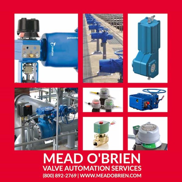
Mead O'Brien can handle any valve actuation requirement you have. Contact them by calling (800) 892-2769 or by visiting https://meadobrien.com.