Decarbonization and Industrial Plant Steam Production and Management

Decarbonization and Industrial Plant Steam Production and Management

Decarbonization is the process of reducing the carbon emissions of an industrial process plant, with the goal of mitigating the negative impacts of climate change. There are several approaches that industrial process plants can take to decarbonize their operations:
  • Energy efficiency: Improving the efficiency of energy-consuming processes can help to reduce the amount of energy needed to operate the plant, which can in turn reduce carbon emissions. This can be achieved through a variety of measures, such as upgrading equipment, optimizing process control, and implementing energy-saving technologies.
  • Renewable energy: Replacing fossil fuel energy sources with renewable energy sources, such as solar, wind, and hydroelectric power, can help to reduce carbon emissions from the plant.
  • Carbon capture and storage: Carbon capture and storage (CCS) technologies capture carbon dioxide emissions from industrial processes and store them underground, preventing them from being released into the atmosphere. While CCS is still in the early stages of development, it has the potential to significantly reduce carbon emissions from industrial process plants.
  • Process optimization: Optimizing the processes used in the plant can help to reduce energy consumption and carbon emissions. This can be achieved through process redesign, process integration, and other techniques that improve efficiency and reduce waste.
  • Process substitution: Replacing high-carbon processes with lower-carbon alternatives can help to reduce the overall carbon emissions of the plant. For example, a plant that uses coal to generate electricity could switch to natural gas, which has lower carbon emissions per unit of energy produced.
In the context of steam process heating, decarbonization can be achieved through a variety of approaches, such as:
  • Switching to a low-carbon or carbon-neutral fuel source: One way to decarbonize steam process heating is to switch from a fossil fuel, such as natural gas or coal, to a low-carbon or carbon-neutral fuel source, such as biomass or biogas. This can significantly reduce the carbon emissions of the steam process heating system.
  • Improving energy efficiency: Another way to decarbonize steam process heating is to focus on improving the energy efficiency of the system. This can be achieved through various measures such as insulating steam pipes, using energy-efficient boilers, and optimizing the steam distribution system.
  • Capturing and storing carbon emissions: In some cases, it may not be possible to completely eliminate carbon emissions from steam process heating. In such cases, capturing and storing the emissions through techniques such as carbon capture and storage (CCS) can help to mitigate their impact on the environment.
  • Using renewable energy sources: Another option for decarbonizing steam process heating is to use renewable energy sources, such as solar, wind, or hydroelectric power, to generate the steam. This can greatly reduce the carbon emissions associated with the process.

Overall, decarbonization of industrial process plants requires a combination of approaches, depending on the specific circumstances of the plant and its operations.

Mead O'Brien will provide expert consultation and advisory services to assist you in reducing your carbon footprint in the production and management of steam. Call them at (800) 892-2769 or visit https://meadobrien.com.

Jamesbury™ Quadra-Powr™ Spring Diaphragm Quarter Turn Actuators for Use in Both Modulating Control and On-Off Service

Jamesbury™ Quadra-Powr™ Spring Diaphragm Quarter Turn Actuators

Valves provide pressure reduction and flow control through piping systems and are critical to industries that form the backbone of the modern world. The valve actuator is crucial for valve operation. Actuators are powered devices that move valves between open and closed states. The valves can open or close depending on the movement it receives from an actuator; this motion is responsible for controlling the flow and pressure within an industrial system or process.

Jamesbury™ Quadra-Powr™ spring diaphragm QPX series quarter turn actuators are applicable for modulating control and on-off service. These actuators offer an exceptionally long cycle life and are well-suited to operate almost any type of rotary valve. The QPX actuator provides smooth and efficient quarter-turn valve operation and safe and reliable operation even when minimal supply pressure is available.

Exclusively developed for quarter-turn valve service, Quadra-Powr™ X spring-diaphragm actuators provide safe and reliable operation even when minimal supply pressures are available. Yet they can operate at pressures as high as 7 bar (100 psi).

These units operate by air, gas, water, oil, or other supply media compatible with the actuator's ductile iron/carbon steel casing and the Buna-N diaphragm reinforced with polyamide fabric. This unique spring-diaphragm actuator for rotary valves provides safe, smooth, and reliable valve actuation at minimal pressures and up to 100 psi (6.9 BAR). Quadra-Powr X torque outputs range from 15 to 796 Nm (11 to 587 ft-lbs), depending on actuator selection and available supply pressure.

Jamesbury™ Quadra-Powr™ Features:
  • Rolling diaphragm for minimum friction
  • Low friction bearings – factory lubricated for lifetime
  • Field reversible for spring to open or close simply by flipping actuator over
  • Safety contained springs prevent hazards of inadvertent ejection during maintenance
  • Corrosion resistant – two layer epoxy and polyurethane paint with stainless steel fasteners
  • Adjustable stops for both open and closed positions
  • Wide input pressure range – up to 7 bar (100 psi)
For more information, contact Mead O'Brien. Call (800) 874-9655 or visit https://meadobrien.com.

Industrial Actuators, Valves, and Positioners

Industrial Actuators, Valves, and Positioners

Valves regulate fluid flow to provide accurate control and safety in any given process system, and methods of adjusting valve position are always required.


Commonly, valves are operated with handwheels or levers, although some must be regularly opened, closed, or throttled. In certain conditions, it is not always practical to position valves manually; hence actuators are employed instead of hand wheels or levers. 


An actuator is a mechanism that moves or regulates a device, such as a valve. Actuators decrease the requirement for people to operate each valve manually. Valves using actuators can remotely control valve position, particularly crucial in applications where valves open and close or modulate fast and precisely. 


Pneumatic, hydraulic, and electrical actuators are the three fundamental types. 


  1. Pneumatic actuators employ air pressure to generate motion and are probably the most prevalent type of actuator utilized in process systems. 
  2. Actuators powered by a pressurized fluid, such as hydraulic fluid, are called hydraulic actuators. Typically, hydraulic actuators of the same size produce more torque than pneumatic actuators. 
  3. Electric actuators generate motion using electricity. Actuators usually belong to two broad categories: solenoid or motor-driven actuators. 


Actuators position valves in response to controller signals and can be positioned rapidly and precisely to accommodate frequent flow variations. The instrumentation systems that monitor and respond to fluctuations in plant processes include controllers. Controllers receive input from other instrumentation system components, compare that input to a setpoint, and provide a corrective signal to bring the process variable (such as temperature, pressure, level, or flow). 


You have a control valve when actuators pair with flow-limiting or flow-regulating valves. Generally speaking, control valves automatically restrict flow to provide accurate flow to a process to maintain product quality and safety. 


Control valves can be linear, where the stem moves the valve disk up and down like globe valves, or rotational. Rotary control valves include butterfly valves, which open or close with a 90-degree rotation. The pneumatic diaphragm and electric actuators are the most prevalent on linear and rotational control valves.


Some valves require long stem travel or substantial force to change position. A piston actuator's higher torque is preferable to diaphragm actuators in these situations. Examples of piston actuators are rack and pinion and scotch-yoke designs. 


Single-acting piston actuators control the air pressure on one side of a piston, and with higher air pressure, the piston moves within the cylinder and turns the valve. The air on the opposite side of the piston exits the cylinder via an air vent. With decreased air pressure, the spring expands, causing the piston to move in the opposite direction. 


If air pressure falls below a predetermined threshold or is lost, the spring will push the piston to the desired position, referred to as the "fail" position (open or closed). 


A double-acting piston actuator lacks a spring and has air supply ports on both ends of the cylinder. Increasing air pressure to the supply port moves the valve in one direction. Higher pressure air entering from the opposite supply port pushes the valve in the opposite direction. Filling the cylinder with air and releasing air from the cylinder is regulated by a device known as a positioner. 


Typically, the control of pneumatic actuators occurs from air signals from a controller. Some actuators react directly from a controller, for instance, a pneumatic 3-15 PSI controller output. Sometimes, a controller signal alone cannot counteract a valve's friction or the process media's fluid pressure. This situation requires a separate, high pressure air supply and modulating it with a pneumatic or electro-pneumatic positioner. These devices regulate a high pressure air supply to ensure that an actuator has enough torque to position a valve accurately. The positioner responds to a change in the controller's air, voltage, or current signal and proportions the high pressure air to the actuator. Connecting the actuator stem to the positioner is a mechanical linkage. This mechanical connection is also known as a feedback connection. The link moves as the actuator stem moves up, down, or rotationally. The location of the connection informs the positioner when sufficient movement coincides with the controller's air signal. The controller's signal transmits to the positioner instead directly to the actuator, and the positioner regulates the air supply provided to the actuator.


Like other process components, actuators are prone to mechanical issues. Since actuator issues can negatively impact the operation of a process, it is essential to be able to recognize actuator issues when they occur. Frequently, an operator can notice an actuator fault by comparing the valve position indication to the position specified by the controller. For instance, if the position indicator shows the valve closed, but the flow indicator on the controller indicates that flow is still passing through the valve, the valve seat and disc are likely worn, enabling leakage through the valve.


Because there are so many different styles and designs of actuators, positioners, and valves and so many industrial applications, the combination possibility matrix is vast. You must discuss your application with a knowledgeable, experienced valve expert. The success of your project in terms of product quality, system cost, maintenance, and safety depends upon it.


Mead O'Brien
(800) 874-9655

Setting the Foxboro/Schneider Electric IDP10-A Differential Pressure Transmitter for Measuring Flow


This tutorial explains the setup for the Foxboro / Schneider Electric differential pressure transmitter model IDP10-A when used in a flow monitoring application.

When you need the flexibility and performance of a customizable, intelligent transmitter but do not need a digital output signal, these transmitters give outstanding value at a low cost. 

The Foxboro® brand Model IDP10 is a two-wire d/p Cell® Transmitter with an analog output that enables accurate, dependable differential pressure measurement and transmits a 4 to 20 mA analog output signal. 

The IDP10 is a comprehensive series of d/p Cell, gauge, absolute, multirange, multivariable, and premium performance transmitters. All use field-proven silicon strain gauge sensors and standard top works. 

Included in this transmitter is the -A electronics module. It is a low-cost analog output transmitter with complete configurable capabilities. This transmitter offers the most ability at the lowest possible cost to you. It even allows you to re-calibrate to new calibrated ranges using the conventional LCD indication without the requirement for calibration pressure. 

It is intended for use in Division 1 hazardous locations and meets Division 2 standards. Versions that fulfill agency flameproof and zone criteria are also available.

For more information, contact Mead O'Brien. Call (800) 874-9655 or visit https://meadobrien.com.

The Armstrong VERIS Verabar®


Veris Verabar Mead O'Brien
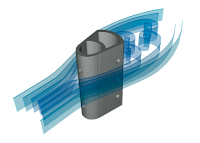
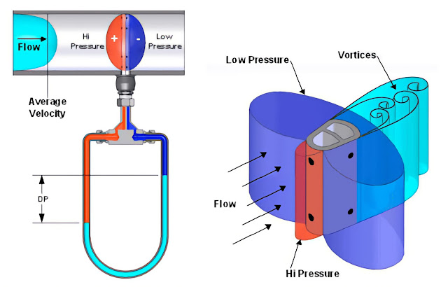
The Armstrong Veris Verabar averaging pitot flow sensor provides unsurpassed accuracy and reliability. With its solid one-piece construction and bullet shape, the Verabar makes flow measurement clog-free and precise. Its unique sensor shape reduces drag and flow-induced vibration, and the location of the low-pressure ports eliminates the potential for clogging and improves signal stability.

Veris Verabar Flow

Veris Verabar Mead O'Brien
Verabar - Superior Signal Stability and Greater Resistance to Clogging

Clogging can occur in low-pressure ports in or near the partial vacuum at the rear of the sensor. The Verabar design finds the low-pressure ports on the sides of the sensor, forward of the fluid separation point, and turbulent wake area, virtually eliminating clogging and producing an extremely stable signal.

Verabar - Flow Coefficient
Verabar - Accuracy You Can Trust And the Data to Back It Up

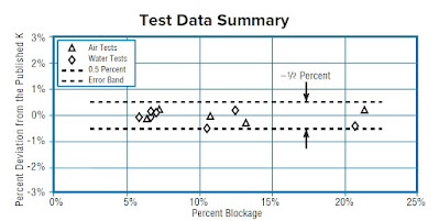
The unique and exclusive breakthrough in improved accuracy derived from developing a verified theoretical model predicts the Verabar flow coefficients. The verified theoretical model eliminates the need for calibration tests to characterize the flow coefficients. Without such a model, the uncertainty of the flow coefficients dramatically increases, and expensive calibration is required. Empirical test data from independent laboratories verified the theoretical model and flow coefficients as a constant, independent of the Reynolds number and within ±0.5% of the predicted value. The Verabar Flow Test Report (ED-100) includes the theoretical model and test data derivation.

Verabar Flow Data


Verabar - Lower Drag and Extended Turndown

Golf balls fly farther because they have a dimpled surface that lowers aerodynamic drag. The grooves and roughness on the Verabar’s frontal surface apply the same principle. This simple design feature relieves the partial vacuum at the rear of the sensor, reducing the pressure drag and extending the accuracy and rangeability to very low velocities.


For more information about VERIS Verabar® contact Mead O'Brien. Call (800) 874-9655 or visit https://meadobrien.com.