The Basics of a Fieldbus Control Network

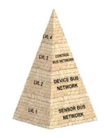
Fieldbus diagram
Computer systems used within the industrial sector are connected by networks known generally as Fieldbus. Fieldbus systems are a way to connect computers and instruments to a single network in a manufacturing plant and allow for real-time control and monitoring. Fieldbus industrial networks can be broken down into four levels each with increasing levels of complexity.

The most basic level is the sensor bus networks. Sensor bus networks are the least complex of networks developed for industrial application. In these networks, multiple basic field devices like limits witches or level optical sensors are connected to one network cable. The sensor bus network is also capable of transmitting output signals from the controller over one cable to indicator lamps, alarms, or other actuator devices.

The next increasingly complex level of industrial Fieldbus networking is the device bus network. The device bus network is similar in function to the sensor bus network but works on a larger scale connecting many sensors and actuators together. The device bus network also connects equipment to variable speed drives and motor control centers that allow for control of individual elements in the network.

Moving up the pyramid, the next increasing complex level of Fieldbus networking is the control bus network. Control bus networks are the most advanced networks used on the factory floor and data communication happens at a high level. PLC's, or programmable logic controllers, are connected to each other alongside HMI's or human machine interface panels to allow for complete configuration and control of every instrument on the network. Smart instruments, capable of performing complex operations, can also be connected at this network level. For instance, there might be a smart instrument that measures wear and tear on a valve. When the wear reaches a dangerous level it will signal the controller that the valve needs to be replaced.

The enterprise or information level network in a company connects all computers and departments together it is the most overarching and complex of all the various network levels. This level of networking is primarily computer driven which allows for data collection, data monitoring, file transfers, and email exchange on a large scale. The various levels of interconnected Fieldbus networking help to keep industry functioning smoothly and successfully.
Process Instrument Calibration and Repair

The Mead O’Brien Instrument Shop is fully equipped to handle your instrument calibration and repair needs. Whether its repair, calibration or certification services, Mead O’Brien can handle the job. Our technicians are factory trained and certified and can repair and re-calibrate virtually any pressure and temperature transmitter, pressure gauge, pressure switch, thermometer, RTD, or thermocouple.

Industrial Pressure Switches

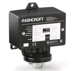
Industrial Pressure Switch
Industrial Pressure Switch (Ashcroft)
A pressure switch is a device that detects the presence of fluid pressure. Pressure switches use a variety of sensing elements such as diaphragms, bellows, bourdon tubes, or pistons. The movement of these sensors, caused by pressure fluctuation, is transferred to a set of electrical contacts to open or close a circuit.

Normal status of a switch is the resting state with stimulation. A pressure switch will be in its “normal” status when it senses low or minimum pressure. For a pressure switch, “normal” status is any fluid pressure below the trip threshold of the switch.

One of the earliest and most common designs of pressure switch was the bourdon tube pressure sensor with mercury switch. When pressure is applied, the bourdon tube flex's enough to tilt the glass bulb of the mercury switch so that the mercury flows over the electrical contacts, thus completing the circuit. the glass bulb tilts far enough to cause the mercury to fall against a pair of electrodes, thus completing an electrical circuit. Many of these pressure switches were sold on steam boilers. While they became a de facto standard, they were sensitive to vibration and breakage of the mercury bulb.
Pressure Switch Symbols

Pressure switches using micro type electrical switches and force-balanced pressure sensors is another common design.  The force provided by the pressure-sensing element against a mechanical spring is balanced until one overcomes the other. The tension on the spring may be adjusted to set the tripping point, thus providing an adjustable setpoint.

One of the criteria of any pressure switch is the deadband or (reset pressure differential). This setting determines the amount of pressure change required to re-set the switch to its normal state after it has tripped.  The “differential” pressure of a pressure switch should not to be confused with differential pressure switch, which actually measures the difference in pressure between two separate pressure ports.

When selecting pressure switches you must consider the electrical requirements (volts, amps, AC or DC), the area classification (hazardous, non-hazardous, general purpose, water-tight), pressure sensing range, body materials that will be exposed to ambient contaminants, and wetted materials (parts that are exposed to the process media).