Coriolis Flowmeter Reduces Sucrose Losses with Better Molasses Production at Sugar Mill

Molasses Production at Sugar Mill
A sugar mill typically loses between one and two percent of its incoming sucrose to factors such as poor clarification, sugar crystal elongation, reduced crystal growth rates, filter cake loss, and loss to molasses. Of these, loss to molasses is most significant — and one of the most difficult to prevent. Loss to molasses results from inaccurate flow measurement that causes more than the required amount of sucrose to pass into the molasses recipe. Wasting valuable sucrose can directly affect profitability of molasses batch yields, so new strategies to control this loss are constantly being investigated.

Improved control begins with a reliable measurement of molasses production, but getting that is indeed a challenge. Estimating undetermined sugar loss to within 0.1 percent, for example, requires molasses loss measurement that is accurate to at least one percent.

There are a number of methods that have been employed to measure molasses quantities in sugar mills around the world, each with distinct advantages and limitations. Measuring storage tank levels on a regular basis is probably the simplest method, but readings are inconsistent and unreliable. The error in the mass estimate affects the undetermined loss directly. Further complicating accuracy are chemical reactions that produce carbon dioxide, which affects both density and tank levels.

Another method is production tank dipping, which involves detecting changes in ow based on changes in torque at various measurement points. While this may be adequate for reporting on a volume basis, most molasses production balance is based on mass. Also, molasses is usually aerated, which creates two-phase flow conditions, further compromising density and accuracy.

Foxboro Coriolis Flowmeter
Engineers at this sugar mill compared measurements made by tank dipping and batch weighing to conventional and digital Coriolis measurements at various points over a three-year period. Years earlier, they installed a competitor’s conventional Coriolis meter. Shortly after, they installed a Foxboro CFT50 digital Coriolis transmitter from Foxboro in series with the existing unit. The Foxboro meter uses digital flowtube control that overcomes flow interruption or stalling caused by two-phase flow. And finally, a short time later, as a benchmark for accuracy, they installed a set of molasses batch scales. Valve leaks notwithstanding, they assumed that the scales would provide the most faithful measure of flow.

The measurements from tank dipping were ten to fifteen percent lower than estimates obtained from either of the Coriolis meters tested.

Later, with the batch scales installed, both Coriolis meters recorded consistently higher estimates than the scales readings. On average, the Foxboro meter gave readings that were three percent higher, and the conventional meter read nine percent higher.

It was clear that the Coriolis meters followed the batch scales much more closely. This strongly indicates the unreliability of tank dipping measurements and suggests that the Coriolis meters are also more responsive to real changes in flow rate. An unanticipated result also indicated that the digital Coriolis meter might be the most responsive to sudden changes in flow rate.

While acknowledging the need for additional study, the researchers concluded that Coriolis measurement is the only suitable alternative to batch scales for measuring sucrose loss to molasses. They found that the conventional Coriolis meter tended to estimate higher than the Foxboro Coriolis meter and that the Foxboro meter had a significantly faster response time in on/off applications.

Conductivity Sensors Improve Biodiesel Production Quality and Production

Biodiesel production improvement
with conductivity sensors.
Biofuel products are made from a variety of feedstocks, primarily soybean oil, vegetable oil and animal fat derivatives. Biodiesel is a safe alternative fuel replacement for traditional petroleum diesel.

The biodiesel production process is done through a chemical reaction that combines vegetable oil or animal fat as a raw stock, methanol, and a catalyst of sodium methylate in proper proportions. The process, called transesterification, involves chemically converting triglycerides to smaller methyl esters that resemble diesel fuel with extra oxygen atoms that make it oxygenated diesel fuel enabling it to burn cleaner.

Producing biodiesel fuel is a difficult task that requires precise separation at various stages. Effective separation is critical to the success of the process and the quality of the product.

The plant has four 20,000-gallon reactors and approximately 15 process vessels of various sizes, as well as large field storage tanks used in the delicate separation process.

When emptying the reactors its very important to know exactly where the interface is between the biodiesel and byproducts. If byproducts are left in the fuel, product quality standards are not met and material have to be reprocessed. If your pour out biodiesel, you’re throwing money down the drain.

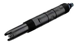
Conductivity sensors
Conductivity sensors (courtesy of Foxboro)
There are a number of ways to detect phase changes, but conductivity sensing seemed ideal for this application. A conductivity measurement system is relatively inexpensive, very clean and maintenance free, since there are no moving parts.

Foxboro, a world-class manufacturer of process control equipment was called in for a consultation. The initial application is in a batch mode where the company has a pump on the bottom of the reactor. Directly downstream of that pump is a “T” configuration that houses the Foxboro conductivity sensor. At this stage, the biodiesel company needs to separate glycerin, which has a relatively high conductivity, approximately 4,000 to 5,000 microsiemen/cm.  The Foxboro probe monitors the conductivity of the fluid passing by and, as the interface occurs, it immediately detects a dramatic drop in conductivity because the methyl ester phase has a conductivity of less than 20 microsiemen/cm. The conductivity sensor then triggers a signal to stop the pump and close the valve. The remainder of what is in the reactor is methyl ester that contains contaminants including excess methanol, glycerin, soaps, catalyst and other impurities.

The second application involves removing these components from the biodiesel fuel before it can be released as a final product. The crude biodiesel is mixed with water to scrub out the impurities, and then the water is allowed to settle to the bottom of the reactor. Because wash water has a high conductivity of about 2,500 microsiemen/cm, the Foxboro sensors can immediately detect the interface between methyl ester and wash water.

After the washing, the biodiesel goes to the final phase where a vacuum dehydrator warms the wet biodiesel and draws out any residual water. In this third application the Foxboro conductivity sensing probe is used to determine when the appropriate amount of water is removed. At that point what remains is finished biodiesel fuel.

Conductivity sensing technology allowed the successful automation of critical phase separation processes and will allow additional and ongoing process improvements such as automated and continuous processing, and further improvements in production efficiencies and more consistent product quality are expected.

Types of Pressure Measurements Used in Process Control

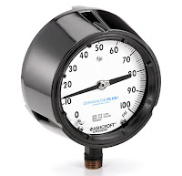
Ashcroft pressure gauge
Pressure gauge
(courtesy of Ashcroft)
Pressure, the measure of a force on a specified area, is a straightforward concept, however, depending on the application, there are many different ways of interpreting the force measurement.

As with any type of measurement, results need to be expressed in a defined and clear way to allow everyone to interpret and apply those results correctly. Accurate measurements and good measurement practices are essential in industrial automation and process environments, as they have a direct effect on the success of the desired outcome.

When measuring pressure, there are multiple units of measurement that are commonly used. Most of these units of measurement can be used with the international system of units, such as kilo, Mega, etc.

This white paper (courtesy of Turck) will identify the various units of pressure measurement, while discussing when and why certain pressure measurements are used in specific applications.

Cybersecurity: Seven Steps to Effectively Defend Industrial Control Systems

Industrial Cybersecurity
Seven steps toward industrial cybersecurity.
Cyber intrusions into US Critical Infrastructure systems are happening with increased frequency. For many industrial control systems (ICSs), it’s not a matter of if an intrusion will take place, but when. In Fiscal Year (FY) 2015, 295 incidents were reported to ICS-CERT, and many more went unreported or undetected. The capabilities of our adversaries have been demonstrated and cyber incidents are increasing in frequency and complexity. Simply building a network with a hardened perimeter is no longer adequate. Securing ICSs against the modern threat requires well-planned and well-implemented strategies that will provide network defense teams a chance to quickly and effectively detect, counter, and expel an adversary. This paper presents seven strategies that can be implemented today to counter common exploitable weaknesses in “as-built” control systems.

If system owners had implemented the strategies outlined in this paper, 98 percent of incidents ICS-CERT responded to in FY 2014 and FY 2015 would have been prevented. The remaining 2 percent could have been identified with increased monitoring and a robust incident response.

1. IMPLEMENT APPLICATION WHITELISTING

Application Whitelisting (AWL) can detect and prevent attempted execution of malware uploaded by adversaries. The static nature of some systems, such as database servers and human-machine interface (HMI) computers, make these ideal candidates to run AWL. Operators are encouraged to work with their vendors to baseline and calibrate AWL deployments.

Example: ICS-CERT recently responded to an incident where the victim had to rebuild the network from scratch at great expense. A particular malware compromised over 80 percent of its assets. Antivirus software was ineffective; the malware had a 0 percent detection rate on VirusTotal. AWL would have provided notification and blocked the malware execution.

2. ENSURE PROPER CONFIGURATION/PATCH MANAGEMENT

Adversaries target unpatched systems. A configuration/patch management program centered on the safe importation and implementation of trusted patches will help keep control systems more secure.
Such a program will start with an accurate baseline and asset inventory to track what patches are needed. It will prioritize patching and configuration management of “PC-architecture” machines used in HMI, database server, and engineering workstation roles, as current adversaries have significant cyber capabilities against these. Infected laptops are a significant malware vector. Such a program will limit connection of external laptops to the control network and preferably supply vendors with known-good company laptops. The program will also encourage initial installation of any updates onto a test system that includes malware detection features before the updates are installed on operational systems.

Example: ICS-CERT responded to a Stuxnet infection at a power generation facility. The root cause of the infection was a vendor laptop.

Use best practices when downloading software and patches destined for your control network. Take measures to avoid “watering hole” attacks. Use a web Domain Name System (DNS) reputation system. Get updates from authenticated vendor sites. Validate the authenticity of downloads. Insist that vendors digitally sign updates, and/or publish hashes via an out-of-bound communications path, and use these to authenticate. Don’t load updates from unverified sources.

Example: HAVEX spread by infecting patches. With an out-of-band communication path for patch hashes, such as a blast email, users could have validated that the patches were not authentic.

3. REDUCE YOUR ATTACK SURFACE AREA

Isolate ICS networks from any untrusted networks, especially the Internet.b Lock down all unused ports. Turn off all unused services. Only allow real-time connectivity to external networks if there is a defined business requirement or control function. If one-way communication can accomplish a task, use optical separation (“data diode”). If bidirectional communication is necessary, then use a single open port over a restricted network path.

Example: As of 2014, ICS-CERT was aware of 82,000 cases of industrial control systems hardware or software directly accessible from the public Internet. ICS-CERT has encountered numerous cases where direct or nearly direct Internet access enabled a breach. Examples include a US Crime Lab, a Dam, The Sochi Olympic stadium, and numerous water utilities.

4. BUILD A DEFENDABLE ENVIRONMENT

Limit damage from network perimeter breaches. Segment networks into logical enclaves and restrict host-to-host communications paths. This can stop adversaries from expanding their access, while letting the normal system communications continue to operate. Enclaving limits possible damage, as compromised systems cannot be used to reach and contaminate systems in other enclaves. Containment provided by enclaving also makes incident cleanup significantly less costly.

Example: In one ICS-CERT case, a nuclear asset owner failed to scan media entering a Level 3 facility. On exit, the media was scanned, and a virus was detected. Because the asset owner had implemented logical enclaving, only six systems were put at risk and had to be remediated. Had enclaving not been implemented, hundreds of hosts would have needed to be remediated.

If one-way data transfer from a secure zone to a less secure zone is required, consider using approved removable media instead of a network connection. If real-time data transfer is required, consider using optical separation technologies. This allows replication of data without putting the control system at risk.

Example: In one ICS-CERT case, a pipeline operator had directly connected the corporate network to the control network, because the billing unit had asserted it needed metering data. After being informed of a breach by ICS-CERT, the asset owner removed the connection. It took the billing department 4 days to notice the connection had been lost, clearly demonstrating that real-time data were not needed.

5. MANAGE AUTHENTICATION

Adversaries are increasingly focusing on gaining control of legitimate credentials, especially those associated with highly privileged accounts. Compromising these credentials allows adversaries to masquerade as legitimate users, leaving less evidence than exploiting vulnerabilities or executing malware. Implement multi-factor authentication where possible. Reduce privileges to only those needed for a user’s duties. If passwords are necessary, implement secure password policies stressing length over complexity. For all accounts, including system and non-interactive accounts, ensure credentials are unique, and change all passwords at least every 90 days.

Require separate credentials for corporate and control network zones and store these in separate trust stores. Never share Active Directory, RSA ACE servers, or other trust stores between corporate and control networks.

Example: One US Government agency used the same password across the environment for local administrator accounts. This allowed an adversary to easily move laterally across all systems.

6. IMPLEMENT SECURE REMOTE ACCESS

Some adversaries are effective at gaining remote access into control systems, finding obscure access vectors, even “hidden back doors” intentionally created by system operators. Remove such accesses wherever possible, especially modems as these are fundamentally insecure.
Limit any accesses that remain. Where possible, implement “monitoring only” access enforced by data diodes, and do not rely on “read only” access enforced by software configurations or permissions. Do not allow remote persistent vendor connections into the control network. Require any remote access be operator controlled, time limited, and procedurally similar to “lock out, tag out.” Use the same remote access paths for vendor and employee connections; don’t allow double standards. Use two-factor authentication if possible, avoiding schemes where both tokens are similar types and can be easily stolen (e.g., password and soft certificate).

Example: Following these guidelines would have prevented the BlackEnergy intrusions. BlackEnergy required communications paths for initial compromise, installation and “plug in” installation.

7. MONITOR AND RESPOND

Defending a network against modern threats requires actively monitoring for adversarial penetration and quickly executing a prepared response.
Consider establishing monitoring programs in the following five key places:
  1. Watch IP traffic on ICS boundaries for abnormal or suspicious communications.
  2. Monitor IP traffic within the control network for malicious connections or content.
  3. Use host-based products to detect malicious software and attack attempts.
  4. Use login analysis (time and place for example) to detect stolen credential usage or improper access, verifying all anomalies with quick phone calls.
  5. Watch account/user administration actions to detect access control manipulation.
Have a response plan for when adversarial activity is detected. Such a plan may include disconnecting all Internet connections, running a properly scoped search for malware, disabling affected user accounts, isolating suspect systems, and an immediate 100 percent password reset. Such a plan may also define escalation triggers and actions, including incident response, investigation, and public affairs activities.
Have a restoration plan, including having “gold disks” ready to restore systems to known good states.

Example: Attackers render Windows®d based devices in a control network inoperative by wiping hard drive contents. Recent attacks against Saudi AramcoTMe and Sony Pictures demonstrate that quick restoration of such computers is key to restoring an attacked network to an operational state.

Defense against the modern threat requires applying measures to protect not only the perimeter but also the interior. While no system is 100 percent secure, implementing the seven key strategies discussed in this paper can greatly improve the security posture of ICSs.

DISCLAIMER

The information and opinions contained in this document are provided “as is” and without any warranties or guarantees. Reference herein to any specific commercial products, process, or service by trade name, trademark, manufacturer, or otherwise, does not constitute or imply its endorsement, recommendation, or favoring by the United States Government, and this guidance shall not be used for advertising or product endorsement purposes.

ACKNOWLEDGMENT

This document “Seven Steps to Effectively Defend Industrial Control Systems” was written in collaboration, with contributions from subject matter experts working at the Department of Homeland Security (DHS), the Federal Bureau of Investigation (FBI), and the National Security Agency (NSA).
Using Eductors for Non-Powered Tank Mixing

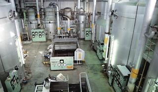
eductor for tank mixing
Eductor for tank mixing
(courtesy of Jacoby Tarbox)
An eductor is a pump that uses a fluid to perform the work of pumping another fluid (or solid). The fluid doing the work is termed the motive fluid, and the fluid being pumped is the suction fluid. The motive fluid employed can be liquid. gas or steam. The suction fluid can be liquid. gas or steam. Other names for eductors include jet pumps, ejectors, Venturi pumps, siphon pumps, steam siphons, and injector pumps. Eductors operate on basic principles of flow dynamics.

Eductors require no power, which means no moving parts. The design of the eductor creates pressure differential allowing fluid to flow naturally within the device - creating suction, mixing, and pushing the liquid throughout the tank.

In-line eductors are the next generation of jet pumps, ejectors, and Venturi pumps providing in-line mixing, pumping, or heating in various process lines. Eductors reduce costs as there are no moving parts and require no direct power.

The video below, while marketing oriented, does a great job at demonstrating how tank mixing is accomplished efficiently and thoroughly with an array of eductors by calculating tank size and volume along with material properties to develop a mixing profile.


For more information, contact:

Mead O'Brien
(800) 892-2769
www.meadobrien.com

Theory of Operation for MOVs (Motor Operated Valves)

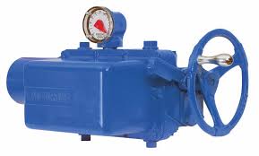
Limitorque SMB MOV
Limitorque SMB MOV
This presentation, provided by the NRC, provides an introductory look at motor operated valves, with a focus on the manufacturer Limitorque. The document includes the theory of operation of MOVs, plus descriptions of valve types, such as gate, globe, ball, plug and butterfly.

This document also provides detailed descriptions of Limitorque SMB actuators and Limitorque SB actuators with full assembly and subassembly breakdown and illustrations.


Document provided by NRC.gov

Configuring a Foxboro PH10 Sensor Using the Foxboro 876PH Transmitter

pH Sensors and ORP Sensors
pH and ORP Sensor
(courtesy of Foxboro)
The PH10 DolpHin® Series pH Sensors and ORP10 DolpHin Series ORP Sensors are suitable for a wide range of pH and ORP measurement applications. They are designed for use with Foxboro® brand 875PH, 873PH, and 873DPX Analyzers, and 876PH Intelligent Transmitters and 870ITPH Transmitters. Some can also be used with 873APH Analyzers. When used with 875PH Analyzers or 876PH and 870ITPH Transmitters, they provide the additional capability of on-line diagnostics to signal the user if any of several common sensor faults occur.

The sensors are available with a choice of temperature compensation and cable termination. They are available with an internal pre-amplifer for use up to 150 m (500 ft) and with a Smart sensor for use up to 100 m (328 ft) from the analyzer or transmitter. The sensors can be mounted to the process in a number of ways. They have a 3/4-inch external NPT connection on both the electrode and cable end. The sensors can be inserted directly into the process line or tank or mounted through a variety of accessories including bushings, tees, flow chambers, and ball valves/insertion assemblies.The sensors are available in both analog and Smart versions.

These industry-leading sensors are already proven in countless installations including chemicals, pulp & paper, all kinds of industry and municipal water/wastewater treatment, metals/mining, and food and dairy applications worldwide.

The Foxboro® brand Model 876PH is a 2-wire loop powered intelligent transmitter that, when used with appropriate electrochemical sensors, provides measurement, local display, and transmission of pH, ORP (Oxidation-Reduction Potential), or ISE (Ion Selective Electrode) concentration. The transmitter outputs a HART digital signal and a 4 to 20 mA analog output. Versions are available for use with both analog and Smart (digital) sensors.

This video demonstrates how to correctly configure a Foxboro® PH10 sensor using the Foxboro® 876PH Transmitter.


Form ore information, contact:

Mead O'Brien
www.meadobrien.com
(800) 892-2769