Providing problem solving and educational information for topics related to industrial steam, hot water systems, industrial valves, valve automation, HVAC, and process automation. Have a question? Give us a call at (800) 892-2769 | www.meadobrien.com
Note:The following post discusses energy consumption and benchmarking in general. As you'll see, the most significant component of plant energy consumption is typically process heating/steam consumption. Mead O'Brien, along with products and technologies from Armstrong International, Shannon Global Energy Solutions and Everactive, has the people, equipment, and experience to assist you in developing a strategy to significantly improve your plant steam and hot water systems conservation efforts. Contact Mead O'Brien for more information.
While each manufacturing facility and production process is unique, every industry uses similar equipment. Most facilities' major energy consumers concentrate energy use on a few basic systems: lighting, process heating, steam generation, compressed air, pumping, and fans. Making a list of Significant Energy Users (SEUs) can assist in focusing efforts on projects that will result in the most significant savings.
To create a list of SEUs, group equipment by location, type, or process, and record information such as estimated operating hours, rated power, and loading. The diagram below depicts the various systems and equipment that consume energy in a typical plant and the differences in potential energy savings between facility systems.
The 80/20 rule applies here. Eighty percent of energy consumption is accounted for by 20 percent of the equipment or processes. Only a few energy systems typically consume most of the energy at a site. Consider concentrating your efforts on these systems.
Comparing facilities, processes, or equipment over time is the baseline.
Benchmarking: Comparing the energy performance of facilities, techniques, or equipment over time to similar internal or external facilities.
Benchmarking the performance of your SEUs is a great place to start on your energy-saving journey. If you work in a multi-facility organization, you can use benchmarking to compare facilities and combine the results to identify best practices. Even if you only have one facility, benchmarking against similar equipment within your facility allows you to identify areas for improvement and best practices of your own.
Benchmarking can include practices such as understanding, comparing, and optimizing maintenance measures and equipment energy use (such as boiler blowdown or compressed air leaks).
Benchmarking your energy data allows manufacturers to compare their equipment, process, or facility to others and identify potential energy savings opportunities. Benchmarking understands how you currently operate (for example, how much energy your plant or a single SEU uses) and compares that to similar operations.
Benchmarking internally (comparing similar steam boilers in the same facility), company-wide (comparing air compressors in different facilities), industry-wide (information from surveys, trade groups, etc.), or all three. Benchmarking can be intimidating for many small manufacturers because, unlike your larger industry peers, you don't have a large pool of plants, manufacturing lines, and heavy equipment for a fair comparison. However, even the smallest manufacturers must compare their major energy users to best practices.
Energy savings occur in systems such as compressed air, steam generation/distribution, or process heating. Determine the types of energy resources used by each piece of machinery or process. A paint booth, for example, will use compressed air to spray the paint, exhaust fans, and process heating to cure the painted product. This activity will aid in the identification of individual energy-consuming systems and their supporting equipment.
Small or medium-sized manufacturers may lack a large energy team, a large budget, or the resources to conduct large-scale energy audits or significant equipment overhauls. Turning to outside experts can be extremely helpful provide proven expertise all for reasonable costs.
Call a Mead O'Brien steam/hot water efficiency expert to help you establish your energy conservation plan.
Mead O'Brien provides the experience and expertise, along with Armstrong's Sage™ IIoT platform and Everactive's battery-less technology, for a completely new energy monitoring and management approach for the process industries.
Consistent with the global move toward sustainability and energy efficiency, Mead O'Brien is proud to join Armstrong International and Everactive. This partnership allows us to work with our customers steam, hot water, and process heating applications in a completely new way. By combining our abilities and technologies jointly, we improve your production process and performance, reduce environmental emissions, increase safety, and help you reach your net-zero carbon goal.
Mead O'Brien, Armstrong International, and Everactive provide the technology and resources to assist you in developing a decarbonization road map customized to your facility and industry. Call us today for more information. 800-874-9655.
Mead O’Brien, Inc. has signed a representative agreement with Armstrong International, a global leader in industrial and institutional steam & water thermal utility systems, to expand into the Western Missouri and Kansas territory.
Mead O'Brien supports customers with application engineering and design consulting of our product portfolio, surveys & assessments, field service, in-house assembly & repair, and training. The extensive product and application knowledge possessed by our sales experts and inside sales product champions are projected into all of our product portfolio territories in the Midwest. Existing Armstrong customers in Western Missouri and Kansas can expect excellent service and product support from our North Kansas City location.
“Our company is excited about our expanded partnership with Armstrong and we are eager to build upon the success our partnership has created over many years in our St. Louis and Calvert City, KY locations. Our vision for this territory expansion will be based upon our culture of dedication to customer, superior service, applied industry knowledge, and our focus on client education. Our mission is to be the technical experts with proven products for our customers with the goal of earning the opportunity to be their trusted advisors”
Ron Morrison, President, Mead O’Brien
“To continue efforts to provide our customers exceptional service and an enjoyable experience, as of October 26, 2020 we have expanded the Mead O’Brien territory to include Western Missouri and the State of Kansas. Mead O’Brien has faithfully represented Armstrong products and customers in Eastern Missouri, Southern Illinois, and Western Kentucky for many years, and their knowledge of thermal utility solutions and services is unmatched. We are confident that their expertise and passion to assist with system solutions will be a true asset to all existing and new customers within this important Midwest region.”
Matt Bloss, Director of North America Sales and Marketing of Armstrong International
Mead O'Brien is a midwestern regional manufacturer's representative and distributor headquartered in North Kansas City, MO with branches, warehouses, and repair facilities in St. Louis, MO; Calvert City, KY; and Tulsa, OK. Sister companies include H*E Engineered Equipment Co., J&M Engineered Products Inc., and Pinnacle Controls LLC. We approach our customers in the process, power, pipeline, HVAC, and the critical infrastructure industries as application specialists in:
Valves, valve automation and control
Steam and hot water products and systems
Instrumentation and controls
Mead O'Brien supports customers with application engineering and design consulting of our product portfolio, surveys & assessments, field service, in-house assembly & repair, and training utilizing our live steam lab. The extensive product and application knowledge possessed by our sales experts and inside product champions are projected into all or parts of ten states in the Midwest including Missouri, Kansas, Nebraska, Iowa, Oklahoma, Arkansas, Southern Illinois, Southwest Indiana, Western Kentucky, and the Texas Panhandle.
CONTACT INFO:
Name: Steve Huffman, Vice President, Marketing & Business Development
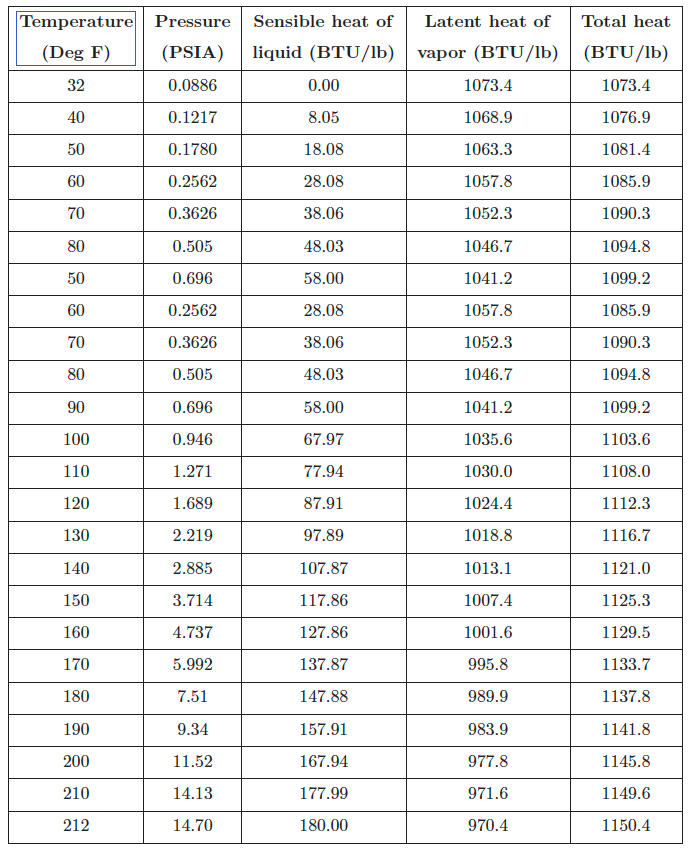
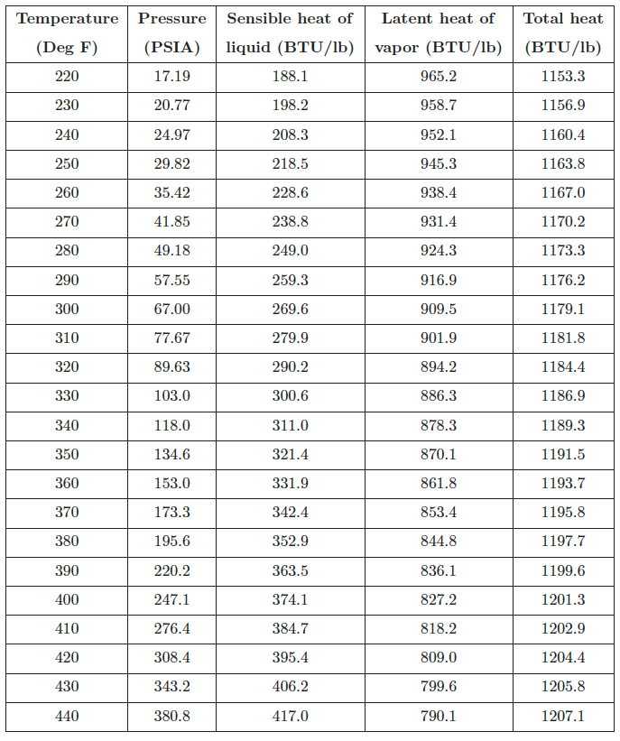
A saturated steam table shows temperatures and pressures for water at the liquid/vapor transition (i.e. points lying along the liquid/vapor interface shown in a phase change diagram), as well as enthalpy values for the water and steam under those conditions. The sensible heat of water is the amount of thermal energy per pound necessary to raise water’s temperature from the freezing point to the boiling point. The latent heat of vapor is the amount of energy per pound necessary to convert water (liquid) into steam (vapor). The total heat is the enthalpy of steam (thermal energy per pound) between the listed condition in the table and the freezing temperature of water.
By definition a saturated steam table does not describe steam at temperatures greater than the boiling point. For such purposes, a superheated steam table is necessary.
Reprinted from "Lessons In Industrial Instrumentation" by Tony R. Kuphaldt – under the terms and conditions of the Creative Commons Attribution 4.0 International Public License. Data for this saturated steam table was taken from Thermal Properties of Saturated and Superheated Steam by Lionel Marks and Harvey Davis, published in 1920 by Longmans, Green, and Company.
Condensate in steam and air piping reduces thermal efficiency, causes water hammer, corrodes equipment such as valves and pipes, and causes other problems.
In-line (drain) separators separate condensate efficiently by using the centrifugal force of steam or air created by introducing it into a specifically shaped path. Because of the simple structure of the drain separators, pressure loss is minimized, enabling clean, dry steam or air to be fed to equipment.
When steam or air flow enters the drain separator, centrifugal force is generated in the fluid because of the device’s internal structural design. The fluid drains along the wall because of the difference in specific gravity with steam or air, eventually striking the baffle. The baffle guides the fluid to the drain outlet and to the trap, which drains it. As a result, small dirt particles and condensate are separated and removed from the system through the bottom drain.
Foxboro Vortex Shedding Flowmeter.
Notice the shedder bar in the flow path.
Photograph of vortices
(credit Jürgen Wagner via Wikipedia)
Vortex shedding flowmeters are a type of flowmeter available to the process industry for the consistent evaluation of flow rates. These flowmeters measure the volumetric flow rate of media such as steam flowing in pipes, gases, and low viscosity liquids, boasting both versatility and dependability. Since they have no moving parts, they are impervious to the kind of wear turbine or mechanical meters experience.
Principles of Operation
A "shedder" bar (also known as a bluff body) in the path of
Animation of vortices
(credit Cesareo de La Rosa Siqueira
via Wikipedia)
the flowing fluid produces flow disturbances called vortices. The resulting vortex trail is predictable and proportional to the fluid flow rate. This phenomena is know as the "Von Kármán vortex street" (see illustrations to the right). Sensitive electronic sensors downstream of the shedder bar measures the frequency of the vortices and produce a small electrical pulse with every vortex created. The electrical pulses also also proportional to fluid velocity and is the basis for calculating a volumetric flow rate, using the cross sectional area of the flow measuring device. Typical Areas of Use
Vortex shedding flowmeters are used on steam, cryogenic liquids, hydrocarbons, air, feed water, and industrial gases. Applications to Avoid
Splitting higher viscosity fluids into concordant vertices is extremely difficult due to the internal friction present, so using vortex shedding flowmeters on high viscosity media should be avoided. Also, avoid applications with low flow rates and low Reynolds Numbers, as the vortices created are unstable.
Consideration for Use
Consideration must be given to applications with low Reynolds numbers, as the generation of vortices declines at critical points of reduced velocity. Low pressure can also be a problem in this regard. Users must take Reynolds number, velocity, and density into consideration before choosing a vortex shedding flow meter. As always, it's best to discuss your application with an knowledgable support professional before specifying, purchasing, or installing this type of flowmeter.
Watch the video below for more information on vortex flow technology.
For more information on vortex shedding flowmeters, visit https://www.meadobrien.com or call (800) 892-2769.
For steam, energy is primarily contained in the latent heat and, to a lesser extent, the sensible heat of the fluid. The latent heat energy is released as the steam condenses to water. Additional sensible heat energy may be released if the condensate is further lowered in temperature. In steam measuring, the energy content of the steam is a function of the steam mass, temperature and pressure. Even after the steam releases its latent energy, the hot condensate still retains considerable heat energy, which may or may not be recovered (and used) in a constructive manner. The energy manager should become familiar with the entire steam cycle, including both the steam supply and the condensate return.
When compared to other liquid flow measuring, the measuring of steam flow presents one of the most challenging measuring scenarios. Most steam flowmeters measure a velocity or volumetric flow of the steam and, unless this is done carefully, the physical properties of steam will impair the ability to measure and define a mass flow rate accurately.
Steam is a compressible fluid; therefore, a reduction in pressure results in a reduction in density. Temperature and pressure in steam lines are dynamic. Changes in the system’s dynamics, control system operation and instrument calibration can result in considerable differences between actual pressure/temperature and a meter’s design parameters. Accurate steam flow measurement generally requires the measurement of the fluid’s temperature, pressure, and flow. This information is transmitted to an electronic device or flow computer (either internal or external to the flow meter electronics) and the flow rate is corrected (or compensated) based on actual fluid conditions.
The temperatures associated with steam flow measurement are often quite high. These temperatures can affect the accuracy and longevity of measuring electronics. Some measuring technologies use close-tolerance moving parts that can be affected by moisture or impurities in the steam. Improperly designed or installed components can result in steam system leakage and impact plant safety. The erosive nature of poor-quality steam can damage steam flow sensing elements and lead to inaccuracies and/or device failure.
The challenges of measuring steam can be simplified measuring the condensed steam, or condensate. The measuring of condensate (i.e., high-temperature hot water) is an accepted practice, often less expensive and more reliable than steam measuring. Depending on the application, inherent inaccuracies in condensate measuring stem from unaccounted for system steam losses. These losses are often difficult to find and quantify and thus affect condensate measurement accuracy.
Volumetric measuring approaches used in steam measuring can be broken down into two operating designs:
Differential pressure
Velocity measuring technologies.
DIFFERENTIAL
For steam three differential pressure flowmeters are highlighted: orifice flow meter, annubar flow meter, and spring-loaded variable area flow meter. All differential pressure flowmeters rely on the velocity-pressure relationship of flowing fluids for operation.
Historically, the orifice flow meter is one of the most commonly used flowmeters to measure steam flow. The orifice flow meter for steam functions identically to that for natural gas flow. For steam measuring, orifice flow flowmeters are commonly used to monitor boiler steam production, amounts of steam delivered to a process or tenant, or in mass balance activities for efficiency calculation or trending.
Differential Pressure – Annubar Flow Meter
The annubar flow meter (a variation of the simple pitot tube) also takes advantage of the velocity-pressure relationship of flowing fluids. The device causing the change in pressure is a pipe inserted into the steam flow.
Differential Pressure – Spring-Loaded Variable Area Flow Meter
The spring-loaded variable area flow meter is a variation of the rotameter. There are alternative configurations but in general, the flow acts against a spring-mounted float or plug. The float can be shaped to give a linear relationship between differential pressure and flow rate. Another variation of the spring-loaded variable area flow meter is the direct in-line variable area flow meter, which uses a strain gage sensor on the spring rather than using a differential pressure sensor.
VELOCITY
The two main type of velocity flowmeters for steam flow, turbine and vortex shedding, both sense some flow characteristic directly proportional to the fluid’s velocity.
Velocity – Turbine Flow Meter
A multi-blade impellor-like device is located in, and horizontal to, the fluid stream in a turbine flow meter. As the fluid passes through the turbine blades, the impellor rotates at a speed related to the fluid’s velocity. Blade speed can be sensed by a number of techniques including magnetic pick-up, mechanical gears, and photocell. The pulses generated as a result of blade rotation are directly proportional to fluid velocity, and hence flow rate.
A vortex-shedding flow meter senses flow disturbances around a stationary body (called a bluff body) positioned in the middle of the fluid stream. As fluid flows around the bluff body, eddies or vortices are created downstream; the frequencies of these vortices are directly proportional to the fluid velocity.
Process heating methodologies can be grouped into four general categories based on the type of fuel consumed:
Steam
Fuel
Electric
Hybrid systems
These technologies are based upon conduction, convection, or radiative heat transfer mechanisms - or some combination of these. In practice, lower-temperature processes tend to use conduction or convection, whereas high-temperature processes rely primarily on radiative heat transfer. Systems using each of the four energy types can be characterized as follows:
STEAM
Tube heat exchanger.
Steam-based process heating systems introduce steam to the process either directly (e.g., steam sparging) or indirectly through a heat transfer mechanism. Large quantities of latent heat from steam can be transferred efficiently at a constant temperature, useful for many process heating applications. Steam-based systems are predominantly used by industries that have a heat supply at or below about 400°F and access to low-cost fuel or byproducts for use in generating the steam. Cogeneration (simultaneous production of steam and electrical power) systems also commonly use steam-based heating systems. Examples of steam-based process heating technologies include boilers, steam spargers, steam-heated dryers, water or slurry heaters, and fluid heating systems.
FUEL
Fuel-based process heating systems generate heat by combusting solid, liquid, or gaseous fuels, then transferring the heat directly or indirectly to the material. Hot combustion gases are either placed in direct contact with the material (i.e., direct heating via convection) or routed through radiant burner tubes or panels that rely on radiant heat transfer to keep the gases separate from the material (i.e., indirect heating). Examples of fuel-based process heating equipment include furnaces, ovens, red heaters, kilns, melters, and high-temperature generators.
ELECTRICITY
Electricity-based process heating systems also transform materials through direct and indirect processes. For example, electric current is applied directly to suitable materials to achieve direct resistance heating; alternatively, high-frequency energy can be inductively coupled to suitable materials to achieve indirect heating. Electricity-based process heating systems are used for heating, drying, curing, melting, and forming. Examples of electricity-based process heating technologies include electric arc furnace technology, infrared radiation, induction heating, radio frequency drying, laser heating, and microwave processing.
HYBRID
Hybrid process heating systems utilize a combination of process heating technologies based on different energy sources and/or heating principles to optimize energy performance and increase overall thermal efficiency. For example, a hybrid boiler system may combine a fuel-based boiler with an electric boiler to take advantage of access to lower off-peak electricity prices. In an example of a hybrid drying system, electromagnetic energy (e.g., microwave or radio frequency) may be combined with convective hot air to accelerate drying processes; selectively targeting moisture with the penetrating electromagnetic energy can improve the speed, efficiency, and product quality as compared to a drying process based solely on convection, which can be rate-limited by the thermal conductivity of the material. Optimizing the heat transfer mechanisms in hybrid systems offers a significant opportunity to reduce energy consumption, increase speed/throughput, and improve product quality.
Any company that is energy conscious is also environmentally conscious. Less energy consumed means less waste, fewer emissions and a healthier environment.
In short, bringing energy and environment together lowers the cost industry must pay for both. By helping companies manage energy, Armstrong and Mead O'Brien products and services are also help protect the environment.
Steam is an invisible gas generated by adding heat energy to water in a boiler. Enough energy must be added to raise the temperature of the water to the boiling point. Then additional energy—without any further increase in temperature—changes the water to steam.
Steam is a very efficient and easily controlled heat transfer medium. It is most often used for transporting energy from a central location (the boiler) to any number of locations in the plant where it is used to heat air, water or process applications.
As noted, additional Btu are required to make boiling water change to steam. These Btu are not lost but stored in the steam ready to be released to heat air, cook tomatoes, press pants or dry a roll of paper.
The heat required to change boiling water into steam is called the heat of vaporization or latent heat. The quantity is different for every pressure/temperature combination, as shown in the steam tables.
Heat flows from a higher temperature level to a lower temperature level in a process known as heat transfer. Starting in the combustion chamber of the boiler, heat flows through the boiler tubes to the water. When the higher pressure in the boiler pushes steam out, it heats the pipes of the distribution system. Heat flows from the steam through the walls of the pipes into the cooler surrounding air. This heat transfer changes some of the steam back into water. That’s why distribution lines are usually insulated to minimize this wasteful and undesirable heat transfer.
When steam reaches the heat exchangers in the system, the story is different. Here the transfer of heat from the steam is desirable. Heat flows to the air in an air heater, to the water in a water heater or to food in a cooking kettle. Nothing should interfere with this heat transfer.
Condensate Drainage - Why It’s Necessary
Condensate is the by-product of heat transfer in a steam system. It forms in the distribution system due to unavoidable radiation. It also forms in heating and process equipment as a result of desirable heat transfer from the steam to the substance heated. Once the steam has condensed and given up its valuable latent heat, the hot condensate must be removed immediately. Although the available heat in a pound of condensate is negligible as compared to a pound of steam, condensate is still valuable hot water and should be returned to the boiler.
Electrically automated gate valve
in generating facility.
Having knowledgeable, experienced and skilled vendor-partners is crucial in mitigating safety, environmental, and health risks, as well as meeting power generation facility construction and production goals. Partnering with the right valve automation company means that you will have industry experts there to ensure the success of your project, meeting your budgetary and performance goals, and passing critical know-how along to your staff.
But what should you look for in a valve automation partner?
Understanding and Meeting Expectations Your valve automation partner needs to understand your industry, the application, and the upstream and downstream processes affected by the automated system being installed. Your partner must have a full understanding of all types of valve automation, including pneumatic, hydraulic, electro-hydraulic, and electric actuation. A full understanding of the morass of technical and administrative requirements is critical. These include a knowledge of applicable codes, industry standards, environmental concerns, maintenance requirements, back-up systems, and emergency processes. A strong candidate will consider all of these factors for every power plant valve automation job.
Engineering, Experience, and Precision
Qualified engineering staff and experience are critically important factors in selecting your valve automation partner. A qualified partner should have engineering staff with decades, not just years, of experience in applying, specifying, designing, and fabricating automated valve systems for the power industry. Additional experience in other industry segments is a plus, but a working history and a proven, successful track record in power plant automation is mandatory. All production technicians should be factory trained with valid certification. Whether a 1/2” ball valve with simple electric actuator, or 48” valve gate with extensive controls, your valve automation partner needs to reliably and consistently ensure conformance to specifications. Involvement
Your valve automation partner needs to remain involved in every step of the process - from specifying, quoting, fabrication, delivery, installation, and training. The best valve automators stand by the customer after the automated valve systems are shipped. They see the project through to completion, paying great attention to detail. They generally obsess over the smallest details. For instance, a critical area is actuator-to-valve adaption design and configuration and a good candidate will pay very close attention to that piece. Good valve automation partners create and provision high quality drawings and wiring diagrams. They carefully ensure all requested settings and configuration meets specification and is completed. Finally, they maniacally Q.C. the completed automated valve though in-depth cycle testing before shipping. A good valve automation partner truly understands that this investment in detail upfront, eliminates costly downstream errors and mistakes. Documentation and Tagging
Your partner should provide very detailed documentation for each automated package. Documentation packages should be very detailed and include valve Cv, actuator sizing calculations, material selection criterion, ISA data-sheets, dimensional drawings, operational testing data, seat leak test data, packing leakage data, and switch setting verification. Your valve automation partner should standardly provide valve packages tagged with stainless steel stamped serial numbers that provide traceability back to original components, fabrication, and testing. Facilities
Your valve automation partner should have in-house capabilities for lifting, moving, testing, and storing large valve assemblies. The facility needs adequate pneumatic and electrical service to power any system they build. The space and ability to move large valves with lifts, hoists, and jacks is important. Storage space for sub-assemblies and finished goods, high pressure leak testing stations, seat leak testing stations. In-house CAD systems and on-premise machine shops provide an environment for better quality control and communication. Close proximity between engineers, designers, and technicians supports efficient communication and full understanding of customer needs. An on-site training room, with all required electrical and pneumatic testing rigs should be available. Finally, large docking facilities and easy access to major highways minimizes transportation issues and lowers cost. Training
Valve automation training facility
(courtesy of Mead O'Brien)
Your plant maintenance crews must have 100% familiarity with the operation, maintenance, and troubleshooting of your new valve systems. Your valve automation partner must have the capability to provide practical, and hands-on, training on all facets of valve automation. Programs must be customizable to customer needs and special situations.
By doing your due diligence, and thoroughly evaluating a prospective valve automation partner, you are establishing a framework of confidence and trust that minimizes risk and provides peace of mind that your critically important power plant valve systems will provide safe, efficient, and reliable performance for years to come.
Do the people who maintain your plant’s steam system really understand how to save you money?
It's probably a good idea to have them attend a professional steam and hot water training seminar. These programs provide a window into elements of the plant steam cycle as they observe live steam and condensate behavior in glass piping and glass-bodied steam traps under differing conditions. They gain very useful knowledge regarding:
Steam generation
Distribution
Control & Heat transfer
Heat Recovery opportunities
Condensate removal & return
Mead O'Brien, a company with decades of experience in industrial and commercial steam and hot water systems provides such training. See their video below:
From sanitization to pasteurization, steam heating is critical in the brewing process and steam boilers are one of the most important investments a brewery will ever make. Understanding boiler components and safe boiler operation is crucial to ensuring the protection of people and property, as well as for maximum operating efficiency and optimal energy savings.
This video contains The Master Brewers Association of the Americas (MBAA.com) recent podcast with Mead O'Brien's Steve Huffman about steam boiler safety, operation, and performance.
Mead O’Brien is recognized as leading experts the industrial and commercial use of steam including industrial and commercial boilers, traps, condensate pumps, temperature and pressure controls, heating coils, and heat exchangers.
Water hammer. It's a familiar sound nearly everyone has heard in their own home when someone slams a faucet closed. You have probably also heard it coming from radiators during the winter heating season. In industrial situations, though, water hammer is more than just a noisy annoyance. Water hammer that results from localized abrupt pressure drops may never be heard. Yet water hammer can acquire great force, damaging equipment, ruining product, and potentially putting personnel at risk.
Water hammer begins when some force accelerates a column of water along an enclosed path. The incompressible nature of water gives it the power of a steel sledge as it slams into elbows, tees, and valves. The resulting vibrations are transmitted along the water column and piping, damaging fittings and equipment far removed from the problem source.
Water hammer can occur in any water supply line, hot or cold, and its effects can be even more pronounced in bi-phase systems. Bi-phase systems contain both condensate and live or flash steam in the same space. Heat exchangers, tracer lines, steam mains, condensate return lines, and in some cases, pump discharge lines, may contain a bi-phase mix.
Three distinct conditions have been identified, which provide the force that initiates water hammer. These conditions, hydraulic shock, thermal shock, and differential shock, are common to many industrial fluid applications. However, following a few simple guidelines will help you minimize the occurrence of these shocks and diminish the chance of damaging water hammer.
Hydraulic shock occurs when a valve is closed too abruptly. When a water valve is open, a solid column of water moves from its source at the main to the valve outlet. This could be 100 pounds of water flowing at 10 feet per second, or about 7 miles per hour. Closing the valve suddenly is like trying to instantly stop a 100-pound hammer. A shockwave of about 6600 psi slams into the valve and rebounds in all directions, expanding the piping and reflecting back and forth along the length of the system until its momentum is dissipated. By closing the valve slowly, the velocity of the water is reduced before the column is stopped. Since the momentum of the water is decreased gradually, damaging water hammer will not be produced.
Sometimes, check valves can produce hydraulic shock. Swing check valves are often used to prevent liquid being drawn into spaces that are subject to intermittent vacuums. They are also applied to prevent back-flow from elevated systems when adequate pressure to raise the liquid cannot be guaranteed. In either case, the acceleration of the reversing column of liquid may be quite high. If the swing length of the check valve is sufficient, the column will build enough inertia to cause hydraulic shock in the time it takes the valve to slam shut. Substitute silent or non-slam check valves for swing checks to prevent water hammer in these situations. Silent check valves are center-guided to provide a much shorter stroke than swing checks. These valves also use a spring to help enclosing. The result is that silent check valves are closed by the loss of upstream pressure rather than the reversal of flow, preventing hydraulic shock.
Water hammer arresters, if correctly sized, placed, and maintained, will reduce water hammer. When the forward motion of the water column is stopped by the valve, part of the reversing column is forced into the water hammer arrester. The water chamber of the arrester expands at a rate controlled by the pressure chamber, gradually slowing the column, and preventing hydraulic shock. To prevent water hammer due to hydraulic shock, avoid suddenly stopping water columns. Ensure slow closure of valves, and install spring-loaded, center-guided, non-slam, or silent check valves that close before flow reversal when appropriate. Use water hammer arresters if necessary, but be sure they are sized and placed correctly, and are well-maintained.
Water hammer may also be initiated by thermal shock. In bi-phase systems, steam bubbles may become trapped in pools of condensate. Since the condensate temperature is usually below saturation, the steam will immediately collapse. Steam occupies hundreds of times the volume of an equal amount of water. When the steam collapses, water is accelerated into the resulting vacuum from all directions. When the void is filled, the water impacts at the center, sending shockwaves in all directions.
One likely place for thermal shock to occur is in steam utility corridors. In these areas, the drip traps from high-pressure steam mains often discharge directly into the pumped condensate return lines. The temperature of the condensate in these lines usually ranges from 140 to 180 degrees Fahrenheit. The condensate being discharged from the steam trap is at nearly steam temperature when it passes through the trap orifice. When the trap discharge enters the low-pressure condensate line, a great deal of it flashes back into steam. The flash steam immediately collapses again when it encounters the relatively cool pump discharge water. This thermal shock often causes damaging water hammer. The localized sudden reduction in pressure near the wall chips away piping and tube interiors. Oxide layers that otherwise would resist further corrosion are removed, resulting in accelerated deterioration of piping and equipment. To minimize such a disturbance, the drip trap should discharge in the direction of condensate flow by means of a special fitting.
This method of controlling thermal shock, called "sparging," reduces the concentration of collapsing steam bubbles, and keeps the action from occurring by the pipe wall. Thermal shock can also occur easily in steam coils if they are constructed as shown here. Since the steam is directed toward the center tube first, it can reach the return header before the top and bottom tubes are filled. Consequently, steam feeds the more remote tubes from both ends. With steam flowing into both ends of a tube, waves of condensate flow toward each other. These waves have the potential of trapping pockets of steam between them. If this happens, thermal shock will result when the pocket of steam collapses and water hammer will probably occur.
Prevent the thermal shock that is generated by such a design by substituting a constant-purge device, such as a differential condensate controller, for the steam trap. Condensate controllers maintain a positive differential pressure across the coil at all times. All the tubes will be fed from the supply end only, preventing the entrapment of steam and the resulting thermal shock. Malfunctioning steam traps may also contribute to thermal shock followed by water hammer. A steam trap that has failed open injects live steam directly into the condensate return line. If this steam is mixed with return line condensate of sufficiently low temperature, it will immediately collapse, and thermal shock will follow.
To prevent the occurrence of water hammer due to thermal shock, you must reduce the concentration of collapsing steam bubbles in the condensate. If flashing condensate must be discharged into a cool condensate line, it should be discharged in the direction of condensate flow and away from the pipe wall. Precautions must be taken that heat exchanger tubes are always filled from the supply end only.
Differential shock, like thermal shock, occurs in bi-phase systems. Differential shock can occur whenever steam and condensate flow in the same line, but at different velocities, such as in high-pressure condensate return lines. In bi-phase systems, the velocity of the steam is often ten times the velocity of the liquid. If this gas flow causes condensate waves to rise and fill the pipe, a seal is formed with the pressure of the steam behind it. Since the steam cannot flow through the condensate seal, pressure drops on the downstream side. The condensate seal now becomes a piston that is accelerated downstream by virtue of this pressure differential. As it is driven downstream, the piston picks up more liquid that is added to the existing mass of the slug, and velocity increases. This is differential shock. If the slug gains high enough momentum, and is then required to change direction at a tee or elbow, or is stopped by a valve, great damage can be done.
In the demo lab at Armstrong International, a fixture was assembled to illustrate the problem with a 20-foot, 2-inch-diameter glass pipe to act as a condensate return line. The pipe is pitched one-quarter inch in 10 feet to provide gravity flow. Flowing through the pipe, we have cold water. In addition to water, we can also have compressed air flowing in the system to simulate flash steam flowing across the top of the condensate by virtue of differential pressure. One flow meter constantly measures the flow rate of the water. Another flow meter continuously monitors the flow rate of the compressed air. As you can see, we now have 1500 pounds per hour of water flowing in our glass pipe, and no compressed air. Under this condition, our pipe is approximately half-filled with water.
As we increase the flow rate of water in our pipe to 2,000 pounds per hour, the depth of the water increases to five-eighths. We now introduce compressed air into the system to simulate flash steam with a flow rate of about 200 standard cubic feet per hour, and the depth of the water recedes. We are increasing the speed of the water flowing through the pipe by virtue of the velocity of the gas flowing across its surface. Observe now as the compressed air flow increases. The waves formed on the surface of the condensate become higher. Further increasing the air flow causes the waves to block off more of the cross section of the piping until a seal is formed, completely closing off the pipe. A slug of condensate is accelerated downstream by the pressure differential, becoming a piston that gains in mass and velocity as it travels. The proper sizing and pitching of condensate lines are the only means of guarding against this type of problem. The Armstrong Steam Conservation Handbook includes a chart that helps you in deciding the correct condensate return line size for your particular application.
Differential shock can also become a problem when elevated heat exchange equipment is drained with a substantial vertical drop ahead of the trap. Under normal conditions, condensate drains down the walls of the pipe. A sufficient volume of steam constantly flows down the center of the pipe to replace the steam that is condensed by radiation losses of the piping and the trap body itself. The steam flow rate increases if a thermostatic element, such as the bellows or wafer in an F & T trap, opens. If a slug of condensate seals off the pipe, steam collapses downstream of the seal. Again, a pressure differential forms, and this, along with gravity, accelerates the slug. When this piston strikes the trap, it can damage the float, the thermostatic element, or other parts of its mechanisms.
To avoid differential shock arising from this situation, use an F & T trap and back-vent it to the top of the vertical line to maintain near-equal pressure throughout the riser, even if a slug of condensate forms. In both of the two previous cases, the condensing of steam downstream of the seal produced the acceleration. It follows that the likelihood of differential shock arising, and causing water hammer, is greater in uninsulated pipes, especially on outdoor systems, than in insulated pipes. Long runs of any kind between the heat exchange equipment and the trap can produce this situation, and should be avoided. Damaging water hammer may also occur due to differential shock whenever there is an improperly-dripped pocket ahead of a control valve. Condensate builds up in front of the valve while it is closed. When the valve is opened, the slug of condensate is driven through the valve and into the piping and equipment by the live steam. The placement of a riser and a drip trap immediately upstream of the control valve will prevent this rampaging slug.
To control differential shock, you must prevent condensate seals from forming in bi-phase systems. Condensate lines must be sized correctly, and long vertical drops to the traps must be back-vented. The length of the lines to traps should be minimized, and the lines may have to be insulated to reduce condensing. The installation of a proper drip leg ahead of control valves will prevent differential shock from occurring when the control valve is opened after a period of closure.
Careful attention to these few guidelines will prevent most water hammer. Prevent the sudden stopping of water in pipelines by closing manual valves slowly, and by installing spring-loaded, center-guided, silent check valves where appropriate. Prevent thermal shock by using a sparging tube wherever flash steam is discharged into condensate at a lower temperature, and by ensuring that heat exchanger tubes are filled from one end. Prevent differential shock in bi-phase systems by providing return lines that are properly pitched and have adequate size. Avoid draining equipment with long lines to the trap, and insulate condensate lines whenever necessary. Following these guidelines for the proper design and operation of your system will minimize the likelihood of the shocks that cause water hammer. This, in turn, will greatly reduce the likelihood of damage to your system, to your product, and to your personnel.
Author: Steve Huffman VP Marketing & Business Development, Mead O'Brien
This article began as a coy reply to Bill Lydon’s interesting “Talk to Me” column (www.isa.org/intech/201512talk) about Leonardo da Vinci’s accomplishments as an artist applying engineering principles to create engineered works of art. Lydon noted that da Vinci saw science and art as complementary rather than as distinct disciplines. I stated that the word “STEAM,” really STEM + art, was not a new concept. The most recent iteration started sometime within the first decade of the 21st century, gaining traction with the efforts of such influencers as the Rhode Island School of Design beginning in 2010. Lawmakers with whom the Automation Federation met while advocating for our profession on Capitol Hill saw the concept as a way to reach elementary school children who would not otherwise be interested in math, science, and engineering.
My point was why use the word “steam” and create confusion with the engine of the American industrial revolution—and still the most efficient turbine driver and heat transfer media in prominent use to this day? Ironically, I find a declining knowledge base regarding steam systems used in industry, especially in process control, as the baby boomers are now retiring at very high levels. New practitioners, automation or otherwise, who either work on or are charged with engineering or maintaining these utility systems for process are generally not well prepared from a knowledge or educational perspective. This issue really adds to the negative financial impact that poorly designed or poorly maintained steam systems contribute to product quality, throughput, and energy loss.
For the artistic, it seems someone should have realized that the word, with all its thermodynamic glory, was already taken. So is it right to add “art” to the critical-thinking process of STEM and to the engineering curriculum to add another dimension to the student’s education? A number of artists and engineers disagree, but mainly because they only view their “discipline” as a tool that makes the other “discipline” superior. In short, it does go both ways, and purists on both sides probably resent that art and engineering go together. Because we come from the engineering side of the fence, I feel that art probably does broaden the horizons of engineers, but bringing art into engineering certainly does nothing to diminish art in and of itself. As art teaches us, there are many ways to comprehend the same thing.
In my own experience with the brewing industry in St. Louis over the past 40 years, the process mix includes engineering, science, and the application of the art of brewing, which goes back to the ancient Greeks. Modern brewing evolved over the past 150 years with people from those disciplines working together, some even using the “glue” of automation to turn their processes into highly automated, high production, and sophisticated dynamos with dozens of new products released yearly, all of them starting with four basic ingredients.
I project that art in STEM (STEM+A if I were chief acronym maker) is absolutely necessary for automation professionals to better appreciate process and better visualize what the future holds. It is also essential for thinking more abstractly, and in homage to the next big thing, developing a critical eye to analyze, put to practical use, and translate from “production-speak” to meaningful “management-speak” the massive amount of data coming our way with the Industrial Internet of Things revolution of which we are on the cusp. Dealing with disruptive technologies in process and factory automation will require digital skills far in excess of what we can even see on the horizon today. It seems that steam may be creating some buzz, but in the future the real kinetic energy will be created by digital engineers.
Steam is the gaseous phase (state) of water and has many domestic, commercial, and industrial uses. There are two categories of steam - wet steam and dry steam. In dry steam, all the water molecules stay in the gaseous state. In wet steam, some of the water molecules have released their energy (latent heat) and begin condensing into water droplets.
Steam, usually created by a boiler burning coal or other fuels, became the primary source of energy for mechanical movement during the industrial revolution, ultimately being replaced by fossil fuels and electricity.
Steam has many commercial and industrial uses. In agricultural, steam is used to remediate and sterilize soil. In power generation, approximately 90% of our electricity is created using steam as the working fluid to spin turbines. Autoclaves use steam for sterilization in microbiology labs, research, and healthcare facilities. Many commercial and industrial pieces of equipment are cleaned with steam. Finally, commercial complexes, campuses and military buildings use steam for heat and humidification.
The following video, the FINAL part of a three part series titled “What Steam Is, How Steam is Used, and the Properties of Steam” provides the viewer with an exceptional basis to build from. Special thanks to Armstrong International who created the original work.
For more information on any industrial or commercial steam application, contact:


 separators")


