Showing posts with label process control. Show all posts

Calibration Procedures for the Ashcroft P-Series Snap Action Switch Pressure Control


The Ashcroft P Series pressure control is a precision device which features a snap action switch. Fixed deadband is available with single or dual SPDT independently adjustable switches with various electrical ratings. Adjustable deadband is available with a SPDT switch with various electrical ratings. Several wetted material constructions for compatibility with pressure media may be obtained.

The “P” Series Ashcroft snap action pressure switch is available in explosion-proof NEMA 7 & 9 configurations. The enclosure is an epoxy coated aluminum casting.

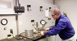
This video describes how to calibrate the Ashcroft P-Series.

For more information about Ashcroft, Inc. products, contact:
Mead O'Brien
https://meadobrien.com
(800) 892-2769

Raising Professional Performance in the Automation Industry

Automation Federation

Steve Huffman, VP of Sales and Marketing for Mead O'Brien, and Greg McMillan, retired Senior Fellow from Solutia/Monsanto and monthly "Control Talk" columnist for Control magazine, discuss the Automation Federation's plans to define needed competencies.

Wireless Process Control Instrumentation

Wireless Process Control Instrumentation
Cost cutting is a fact of life for all industries. Whether it be for more efficient operations, or complying to current regulations, the need to build a better mouse trap is always present.

A very promising cost-cutting technology is wireless instrumentation. Wireless provides a compelling argument to change when you consider installation and overall cost effectiveness. Even more so when the application is located in a harsh environment, or where toxic or combustible situations exist. These robust devices provide critical performance data around the clock in the most inhospitable place in the plant, and operate through rain, wind, high temperatures and high humidity.

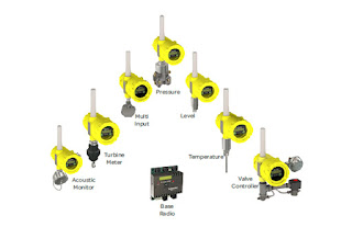
Untethered by cables and hard-wiring, wireless instrumentation is easier to deploy and monitor. Wireless transmitters are available for monitoring virtual all process variables such as pressure, temperature, level, flow, density, and acoustics. Networks of up to 100 (900 MHz) field devices can be created and then monitored by a single base radio or access point, with a typical communication range of over 1/2 mile. By communicating through the industry standard, Modbus, compatibility between device manufacturers is ensured.
Wireless Instrumentation
Wireless Instrumentation (Accutech and Foxboro)

The most obvious reason for choosing wireless over hard-wiring is the cost savings associated with running wires and cables. Savings estimates as high as 70% can be realized by deploying wireless field devices, compared to the same application using cables. Additional savings are realized when you consider that these devices use batteries and that the cost of adding to a network is borne only by the cost of the new device.

Wireless instruments also provide significant benefits in safety and compliance by keeping personnel out of hazardous areas. Areas that would require occasional human visitation can be safely monitored through remote monitoring.

So, what's the hold up? If the benefits are so clear, and the argument is so strong, why is there still reluctance to embrace wireless technology?

There are three main concerns:

Reliability
Wireless instrumentation must provide the same reliability (real and perceived) as traditional wired units. Every engineer, operator and maintenance person knows wires. Troubleshooting wires is easy, and understanding the failures of wires is basic - the wire is either cut or shorted. With wireless however, air is the communication medium and radio signals replace wires. Radio signals are more complicated than wires in terms of potential problems. For instance, signal strength, signal reflection and interference are all possible impediments to reliable links.

The good news is that radio frequency design is continuously improving, and the use of new and advanced technologies, such as frequency hopping receivers and high gain antennas, are enabling wireless devices to create highly reliable links.

Adapting to Existing Infrastructure
Wireless instrumentation networks have to adapt to the existing environment and the placement of structures and equipment. Most times it's just not practical to relocate equipment just to create a reliable wireless link. This can make it challenging to find the optimum location for a base radio or access point that is capable of providing a reliable communication link to your wireless instruments. Furthermore, accommodating the best strategy for one wireless device could negatively affect links with other devices on the same network.

The challenges of adaptability are being overcome by providing better frequency bands (such as 900 MHz). These bands provide longer range, the ability to pass through walls, and offer more saturating coverage. Other ways to overcome adaptability concerns are through the use of external, high gain antennas mounted as physically high as possible, and also by using base radios with improved receiving sensitivity.

Integration with Existing Communications
Engineers, operators, and maintenance crews are challenged by integrating wireless instrumentation networks with other, existing, field communications systems. The issues of having to manage and troubleshoot multiple networks adds levels of complexity to existing systems. This creates a conflict between the financial argument to adopt wireless instrumentation and the possible costs to increase the data gathering capabilities of an existing system. For instance, SCADA systems need to be able to handle the additional data input from wireless devices, but may not have the capacity. Adding the additional data capacity to the SCADA system can be expensive,  and therefore offset the wiring and cabling savings.

The financial argument for industry to adopt wireless instrumentation networks is persuasive, but its acceptance in the process control industry is slow. Reliability, acclimation, and integration are all challenges that must be overcome before widespread adoption occurs. Eventually though, the reality of dramatically reduced deployment and maintenance costs, increased safety, and improved environmental compliance will tip the scale and drive wireless as the standard deployment method.

Always consult with an experienced applications engineer before specifying or installing wireless instrumentation. Their experience and knowledge will save you time, cost, and provide another level of safety and security.

Mead O'Brien: Problem Solver, Innovator, and Best Total Cost Provider

Mead O’Brien specializes in valves & valve automation, steam & hot water products and systems, instrumentation products, skid designs, field services, surveys, assessments, and consulting. The extensive product and application knowledge possessed by the Mead O'Brien sales force projects to all or part of ten states in the Midwest which includes Missouri, Kansas, Nebraska, Iowa, Oklahoma, Arkansas, Texas Panhandle, Southern Illinois, Western Kentucky, and Southwest Indiana.

Process Temperature Sensors: Basics of Thermocouples and RTDs

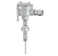
Industrial Thermocouple
(Ashcroft)
Proper temperature sensor selection is key to getting useful and accurate data for maintaining control of a process. There are two main types of temperature sensors employed for industrial applications, thermocouple and resistance temperature detector (RTD). Each has its own set of features that might make it an advantageous choice for a particular application.

Thermocouples consist of a junction formed with dissimilar metal conductors. The contact point of the conductors generates a small voltage that is related to the temperature of the junction. There are a number of metals used for the conductors, with different combinations used to produce an array of temperature ranges and accuracy. A defining characteristic of thermocouples is the need to use extension wire of the same type as the junction wires, in order to assure proper function and accuracy.

Here are some generalized thermocouple characteristics.
  • Various conductor combinations can provide a wide range of operable temperatures (-200°C to +2300°C).
  • Sensor accuracy can deteriorate over time.
  • Sensors are comparatively less expensive than RTD.
  • Stability of sensor output is not as good as RTD.
  • Sensor response is fast due to low mass.
  • Assemblies are generally rugged and not prone to damage from vibration and moderate mechanical shock.
  • Sensor tip is the measuring point.
  • Reference junction is required for correct measurement.
  • No external power is required.
  • Matching extension wire is needed.
  • Sensor design allows for small diameter assemblies. 
RTD sensors are comprised of very fine wire from a range of specialty types, coiled within a protective probe. Temperature measurement is accomplished by measuring the resistance in the coil. The resistance will correspond to a known temperature. 

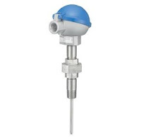
Industrial RTD
Industrial RTD
(Ashcroft)
Some generalized RTD attributes:
  • Sensor provides good measurement accuracy, superior to thermocouple.
  • Operating temperature range (-200° to +850°C) is less than that of thermocouple.
  • Sensor exhibits long term stability.
  • Response to process change can be slow.
  • Excitation current source is required for operation.
  • Copper extension wire can be used to connect sensor to instruments.
  • Sensors can exhibit a degree of self-heating error.
  • Resistance coil makes assemblies less rugged than thermocouples.
  • Cost is comparatively higher.
Each industrial process control application will present its own set of challenges regarding vibration, temperature range, required response time, accuracy, and more. Share your process temperature measurement requirements and challenges with a process control instrumentation specialist, combining your process knowledge with their product application expertise to develop the most effective solution.

The Basics of Process Control Instrument Calibration

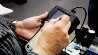
Process Control Instrument CalibrationCalibration is an essential part of keeping process measurement instrumentation delivering reliable and actionable information. All instruments utilized in process control are dependent on variables which translate from input to output. Calibration ensures the instrument is properly detecting and processing the input so that the output accurately represents a process condition. Typically, calibration involves the technician simulating an environmental condition and applying it to the measurement instrument. An input with a known quantity is introduced to the instrument, at which point the technician observes how the instrument responds, comparing instrument output to the known input signal.

Even if instruments are designed to withstand harsh physical conditions and last for long periods of
time, routine calibration as defined by manufacturer, industry, and operator standards is necessary to periodically validate measurement performance. Information provided by measurement instruments is used for process control and decision making, so a difference between an instruments output signal and the actual process condition can impact process output or facility overall performance and safety.

Instrument Calibration LabIn all cases, the operation of a measurement instrument should be referenced, or traceable, to a universally recognized and verified measurement standard. Maintaining the reference path between a field instrument and a recognized physical standard requires careful attention to detail and uncompromising adherence to procedure.

Instrument ranging is where a certain range of simulated input conditions are applied to an instrument and verifying that the relationship between input and output stays within a specified tolerance across the entire range of input values. Calibration and ranging differ in that calibration focuses more on whether or not the instrument is sensing the input variable accurately, whereas ranging focuses more on the instruments input and output. The difference is important to note because re-ranging and re-calibration are distinct procedures.

In order to calibrate an instrument correctly, a reference point is necessary. In some cases, the reference point can be produced by a portable instrument, allowing in-place calibration of a transmitter or sensor. In other cases, precisely manufactured or engineered standards exist that can be used for bench calibration. Documentation of each operation, verifying that proper procedure was followed and calibration values recorded, should be maintained on file for inspection.

As measurement instruments age, they are more susceptible to declination in stability. Any time maintenance is performed, calibration should be a required step since the calibration parameters are sourced from pre-set calibration data which allows for all the instruments in a system to function as a process control unit.

Typical calibration timetables vary depending on specifics related to equipment and use. Generally, calibration is performed at predetermined time intervals, with notable changes in instrument performance also being a reliable indicator for when an instrument may need a tune-up. A typical type of recalibration regarding the use of analog and smart instruments is the zero and span adjustment, where the zero and span values define the instruments specific range. Accuracy at specific input value points may also be included, if deemed significant.

The management of calibration and maintenance operations for process measurement instrumentation is a significant factor in facility and process operation. It can be performed with properly trained and equipped in-house personnel, or with the engagement of highly qualified subcontractors. Calibration operations can be a significant cost center, with benefits accruing from increases in efficiency gained through the use of better calibration instrumentation that reduces task time.

The Basics of a Fieldbus Control Network

Fieldbus diagram
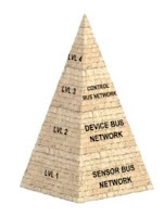
Computer systems used within the industrial sector are connected by networks known generally as Fieldbus. Fieldbus systems are a way to connect computers and instruments to a single network in a manufacturing plant and allow for real-time control and monitoring. Fieldbus industrial networks can be broken down into four levels each with increasing levels of complexity.

The most basic level is the sensor bus networks. Sensor bus networks are the least complex of networks developed for industrial application. In these networks, multiple basic field devices like limits witches or level optical sensors are connected to one network cable. The sensor bus network is also capable of transmitting output signals from the controller over one cable to indicator lamps, alarms, or other actuator devices.

The next increasingly complex level of industrial Fieldbus networking is the device bus network. The device bus network is similar in function to the sensor bus network but works on a larger scale connecting many sensors and actuators together. The device bus network also connects equipment to variable speed drives and motor control centers that allow for control of individual elements in the network.

Moving up the pyramid, the next increasing complex level of Fieldbus networking is the control bus network. Control bus networks are the most advanced networks used on the factory floor and data communication happens at a high level. PLC's, or programmable logic controllers, are connected to each other alongside HMI's or human machine interface panels to allow for complete configuration and control of every instrument on the network. Smart instruments, capable of performing complex operations, can also be connected at this network level. For instance, there might be a smart instrument that measures wear and tear on a valve. When the wear reaches a dangerous level it will signal the controller that the valve needs to be replaced.

The enterprise or information level network in a company connects all computers and departments together it is the most overarching and complex of all the various network levels. This level of networking is primarily computer driven which allows for data collection, data monitoring, file transfers, and email exchange on a large scale. The various levels of interconnected Fieldbus networking help to keep industry functioning smoothly and successfully.

A Magmeter Designed to Withstand the Most Common Failure Modes

Foxboro magnetic flowmeters
Foxboro magnetic flowmeter and transmitter.
When it comes to the application of Magmeters, the biggest problem our customers have is reliability. These devices commonly breakdown due to the corrosive and abrasive materials they measure, and the effects of the internal pressure of the liquid flowing through them.

Foxboro magnetic flowmeters, however, solve these industry-wide issues with superior construction, compact design, the widest selection of options, combined with low power consumption.

Foxboro magnetic flow tubes utilize a superior electrode. By using large electrodes, the flowmeter output is less sensitive to the effects of entrained air, and unaffected by higher internal pressures.

Rugged Teflon liners are resistant to chemical attack which makes it possible to use the Foxboro magnetic flowmeter in hard to handle corrosive liquids and slurries.

Finally, Foxboro magnetic flowmeters offer system  accuracy of plus or minus 0.25 percent of reading.

Foxboro flow tubes can be paired with there IMT 25 and IMT 96 transmitter for complete compact system that provides unequalled durability measurement accuracy and performance with virtually no maintenance and minimal replacement cost covering the widest choice of industry applications available.

For more information on Foxboro magnetic flowmeters please contact Mead O'Brien at (800) 892-2769 or visit http://www.meadobrien.com.

Understanding Differential Pressure or Delta-P

differential pressure
Differential pressure or Delta-P
Commonly, filters and strainers are positioned to capture solids and particulate. The filter will obstruct the flow through the pipe lowering the pressure on the downstream side. These effects may vary depending on the filters construction. Filter media is the material that removes impurities. The smaller the pores the larger the friction. Higher friction means greater pressure drop. Contaminants for particulates that buildup in the filter will reduce media flow. As the filter becomes clogged the downstream pressure drops. This results in an increased differential pressure, also referred to as the Delta-P. Saturated filters may also begin to shed captured particles.

With the filter no longer functioning properly, the contaminants can escape into the process. This is why proper monitoring of pressure drop is crucial. So how can we measure the DP? Placing taps both before and after the filter, a differential pressure measuring instrument can be connected to detect the high side and close side pressures. the instrument will report the difference between the two sides. The saturation point will be indicated when the Delta-P value reaches a predetermined threshold. This value is derived from a calculation that factors in the flow rate, fluid viscosity, and filter characteristics.

When specifying a differential pressure instrument there are two important factors to consider. The first is the DP range, which is based upon the most difference in pressure that the restriction is likely to produce. The second is the instruments ability to contain the line or static pressure level.

For more information on pressure measurement, call Mead O-Brien at (800) 892-2769 or visit www.meadobrien.com.

Here is a great video, courtesy of Ashcroft, that provides an excellent visual understanding of differential pressure.


Types of Pressure Measurements Used in Process Control

Ashcroft pressure gauge
Pressure gauge
(courtesy of Ashcroft)
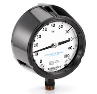
Pressure, the measure of a force on a specified area, is a straightforward concept, however, depending on the application, there are many different ways of interpreting the force measurement.

As with any type of measurement, results need to be expressed in a defined and clear way to allow everyone to interpret and apply those results correctly. Accurate measurements and good measurement practices are essential in industrial automation and process environments, as they have a direct effect on the success of the desired outcome.

When measuring pressure, there are multiple units of measurement that are commonly used. Most of these units of measurement can be used with the international system of units, such as kilo, Mega, etc.

This white paper (courtesy of Turck) will identify the various units of pressure measurement, while discussing when and why certain pressure measurements are used in specific applications.

Cybersecurity: Seven Steps to Effectively Defend Industrial Control Systems

Industrial Cybersecurity
Seven steps toward industrial cybersecurity.
Cyber intrusions into US Critical Infrastructure systems are happening with increased frequency. For many industrial control systems (ICSs), it’s not a matter of if an intrusion will take place, but when. In Fiscal Year (FY) 2015, 295 incidents were reported to ICS-CERT, and many more went unreported or undetected. The capabilities of our adversaries have been demonstrated and cyber incidents are increasing in frequency and complexity. Simply building a network with a hardened perimeter is no longer adequate. Securing ICSs against the modern threat requires well-planned and well-implemented strategies that will provide network defense teams a chance to quickly and effectively detect, counter, and expel an adversary. This paper presents seven strategies that can be implemented today to counter common exploitable weaknesses in “as-built” control systems.

If system owners had implemented the strategies outlined in this paper, 98 percent of incidents ICS-CERT responded to in FY 2014 and FY 2015 would have been prevented. The remaining 2 percent could have been identified with increased monitoring and a robust incident response.

1. IMPLEMENT APPLICATION WHITELISTING

Application Whitelisting (AWL) can detect and prevent attempted execution of malware uploaded by adversaries. The static nature of some systems, such as database servers and human-machine interface (HMI) computers, make these ideal candidates to run AWL. Operators are encouraged to work with their vendors to baseline and calibrate AWL deployments.

Example: ICS-CERT recently responded to an incident where the victim had to rebuild the network from scratch at great expense. A particular malware compromised over 80 percent of its assets. Antivirus software was ineffective; the malware had a 0 percent detection rate on VirusTotal. AWL would have provided notification and blocked the malware execution.

2. ENSURE PROPER CONFIGURATION/PATCH MANAGEMENT

Adversaries target unpatched systems. A configuration/patch management program centered on the safe importation and implementation of trusted patches will help keep control systems more secure.
Such a program will start with an accurate baseline and asset inventory to track what patches are needed. It will prioritize patching and configuration management of “PC-architecture” machines used in HMI, database server, and engineering workstation roles, as current adversaries have significant cyber capabilities against these. Infected laptops are a significant malware vector. Such a program will limit connection of external laptops to the control network and preferably supply vendors with known-good company laptops. The program will also encourage initial installation of any updates onto a test system that includes malware detection features before the updates are installed on operational systems.

Example: ICS-CERT responded to a Stuxnet infection at a power generation facility. The root cause of the infection was a vendor laptop.

Use best practices when downloading software and patches destined for your control network. Take measures to avoid “watering hole” attacks. Use a web Domain Name System (DNS) reputation system. Get updates from authenticated vendor sites. Validate the authenticity of downloads. Insist that vendors digitally sign updates, and/or publish hashes via an out-of-bound communications path, and use these to authenticate. Don’t load updates from unverified sources.

Example: HAVEX spread by infecting patches. With an out-of-band communication path for patch hashes, such as a blast email, users could have validated that the patches were not authentic.

3. REDUCE YOUR ATTACK SURFACE AREA

Isolate ICS networks from any untrusted networks, especially the Internet.b Lock down all unused ports. Turn off all unused services. Only allow real-time connectivity to external networks if there is a defined business requirement or control function. If one-way communication can accomplish a task, use optical separation (“data diode”). If bidirectional communication is necessary, then use a single open port over a restricted network path.

Example: As of 2014, ICS-CERT was aware of 82,000 cases of industrial control systems hardware or software directly accessible from the public Internet. ICS-CERT has encountered numerous cases where direct or nearly direct Internet access enabled a breach. Examples include a US Crime Lab, a Dam, The Sochi Olympic stadium, and numerous water utilities.

4. BUILD A DEFENDABLE ENVIRONMENT

Limit damage from network perimeter breaches. Segment networks into logical enclaves and restrict host-to-host communications paths. This can stop adversaries from expanding their access, while letting the normal system communications continue to operate. Enclaving limits possible damage, as compromised systems cannot be used to reach and contaminate systems in other enclaves. Containment provided by enclaving also makes incident cleanup significantly less costly.

Example: In one ICS-CERT case, a nuclear asset owner failed to scan media entering a Level 3 facility. On exit, the media was scanned, and a virus was detected. Because the asset owner had implemented logical enclaving, only six systems were put at risk and had to be remediated. Had enclaving not been implemented, hundreds of hosts would have needed to be remediated.

If one-way data transfer from a secure zone to a less secure zone is required, consider using approved removable media instead of a network connection. If real-time data transfer is required, consider using optical separation technologies. This allows replication of data without putting the control system at risk.

Example: In one ICS-CERT case, a pipeline operator had directly connected the corporate network to the control network, because the billing unit had asserted it needed metering data. After being informed of a breach by ICS-CERT, the asset owner removed the connection. It took the billing department 4 days to notice the connection had been lost, clearly demonstrating that real-time data were not needed.

5. MANAGE AUTHENTICATION

Adversaries are increasingly focusing on gaining control of legitimate credentials, especially those associated with highly privileged accounts. Compromising these credentials allows adversaries to masquerade as legitimate users, leaving less evidence than exploiting vulnerabilities or executing malware. Implement multi-factor authentication where possible. Reduce privileges to only those needed for a user’s duties. If passwords are necessary, implement secure password policies stressing length over complexity. For all accounts, including system and non-interactive accounts, ensure credentials are unique, and change all passwords at least every 90 days.

Require separate credentials for corporate and control network zones and store these in separate trust stores. Never share Active Directory, RSA ACE servers, or other trust stores between corporate and control networks.

Example: One US Government agency used the same password across the environment for local administrator accounts. This allowed an adversary to easily move laterally across all systems.

6. IMPLEMENT SECURE REMOTE ACCESS

Some adversaries are effective at gaining remote access into control systems, finding obscure access vectors, even “hidden back doors” intentionally created by system operators. Remove such accesses wherever possible, especially modems as these are fundamentally insecure.
Limit any accesses that remain. Where possible, implement “monitoring only” access enforced by data diodes, and do not rely on “read only” access enforced by software configurations or permissions. Do not allow remote persistent vendor connections into the control network. Require any remote access be operator controlled, time limited, and procedurally similar to “lock out, tag out.” Use the same remote access paths for vendor and employee connections; don’t allow double standards. Use two-factor authentication if possible, avoiding schemes where both tokens are similar types and can be easily stolen (e.g., password and soft certificate).

Example: Following these guidelines would have prevented the BlackEnergy intrusions. BlackEnergy required communications paths for initial compromise, installation and “plug in” installation.

7. MONITOR AND RESPOND

Defending a network against modern threats requires actively monitoring for adversarial penetration and quickly executing a prepared response.
Consider establishing monitoring programs in the following five key places:
  1. Watch IP traffic on ICS boundaries for abnormal or suspicious communications.
  2. Monitor IP traffic within the control network for malicious connections or content.
  3. Use host-based products to detect malicious software and attack attempts.
  4. Use login analysis (time and place for example) to detect stolen credential usage or improper access, verifying all anomalies with quick phone calls.
  5. Watch account/user administration actions to detect access control manipulation.
Have a response plan for when adversarial activity is detected. Such a plan may include disconnecting all Internet connections, running a properly scoped search for malware, disabling affected user accounts, isolating suspect systems, and an immediate 100 percent password reset. Such a plan may also define escalation triggers and actions, including incident response, investigation, and public affairs activities.
Have a restoration plan, including having “gold disks” ready to restore systems to known good states.

Example: Attackers render Windows®d based devices in a control network inoperative by wiping hard drive contents. Recent attacks against Saudi AramcoTMe and Sony Pictures demonstrate that quick restoration of such computers is key to restoring an attacked network to an operational state.

Defense against the modern threat requires applying measures to protect not only the perimeter but also the interior. While no system is 100 percent secure, implementing the seven key strategies discussed in this paper can greatly improve the security posture of ICSs.

DISCLAIMER

The information and opinions contained in this document are provided “as is” and without any warranties or guarantees. Reference herein to any specific commercial products, process, or service by trade name, trademark, manufacturer, or otherwise, does not constitute or imply its endorsement, recommendation, or favoring by the United States Government, and this guidance shall not be used for advertising or product endorsement purposes.

ACKNOWLEDGMENT

This document “Seven Steps to Effectively Defend Industrial Control Systems” was written in collaboration, with contributions from subject matter experts working at the Department of Homeland Security (DHS), the Federal Bureau of Investigation (FBI), and the National Security Agency (NSA).

Configuring a Foxboro PH10 Sensor Using the Foxboro 876PH Transmitter

pH Sensors and ORP Sensors
pH and ORP Sensor
(courtesy of Foxboro)
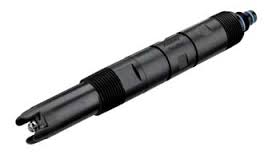
The PH10 DolpHin® Series pH Sensors and ORP10 DolpHin Series ORP Sensors are suitable for a wide range of pH and ORP measurement applications. They are designed for use with Foxboro® brand 875PH, 873PH, and 873DPX Analyzers, and 876PH Intelligent Transmitters and 870ITPH Transmitters. Some can also be used with 873APH Analyzers. When used with 875PH Analyzers or 876PH and 870ITPH Transmitters, they provide the additional capability of on-line diagnostics to signal the user if any of several common sensor faults occur.

The sensors are available with a choice of temperature compensation and cable termination. They are available with an internal pre-amplifer for use up to 150 m (500 ft) and with a Smart sensor for use up to 100 m (328 ft) from the analyzer or transmitter. The sensors can be mounted to the process in a number of ways. They have a 3/4-inch external NPT connection on both the electrode and cable end. The sensors can be inserted directly into the process line or tank or mounted through a variety of accessories including bushings, tees, flow chambers, and ball valves/insertion assemblies.The sensors are available in both analog and Smart versions.

These industry-leading sensors are already proven in countless installations including chemicals, pulp & paper, all kinds of industry and municipal water/wastewater treatment, metals/mining, and food and dairy applications worldwide.

The Foxboro® brand Model 876PH is a 2-wire loop powered intelligent transmitter that, when used with appropriate electrochemical sensors, provides measurement, local display, and transmission of pH, ORP (Oxidation-Reduction Potential), or ISE (Ion Selective Electrode) concentration. The transmitter outputs a HART digital signal and a 4 to 20 mA analog output. Versions are available for use with both analog and Smart (digital) sensors.

This video demonstrates how to correctly configure a Foxboro® PH10 sensor using the Foxboro® 876PH Transmitter.


Form ore information, contact:

Mead O'Brien
www.meadobrien.com
(800) 892-2769

Pneumatic Instruments

pneumatic transmitters
Pneumatic transmitters
(courtesy of Foxboro)
Air pressure may be used as an alternative signaling medium to electricity. Imagine a pressure transmitter designed to output a variable air pressure according to its calibration rather than a variable electric current. Such a transmitter would have to be supplied with a source of constant-pressure compressed air instead of an electric voltage, and the resulting output signal would be conveyed to the indicator via tubing instead of wires:


The indicator in this case would be a special pressure gauge, calibrated to read in units of process pressure although actuated by the pressure of clean compressed air from the transmitter instead of directly by process fluid. The most common range of air pressure for industrial pneumatic instruments is 3 to 15 PSI. An output pressure of 3 PSI represents the low end of the process measurement scale and an output pressure of 15 PSI represents the high end of the measurement scale. Applied to the previous example of a transmitter calibrated to a range of 0 to 250 PSI, a lack of process pressure would result in the transmitter outputting a 3 PSI air signal and full process pressure would result in an air signal of 15 PSI. The face of this special “receiver” gauge would be labeled from 0 to 250 PSI, while the actual mechanism would operate on the 3 to 15 PSI range output by the transmitter. As with the 4-20 mA loop, the end-user need not know how the information gets transmitted from the process to the indicator. The 3-15 PSI signal medium is once again transparent to the operator.

Typically, a 3 PSI pressure value represents 0% of scale, a 15 PSI pressure value represents 100% of scale, and any pressure value in between 3 and 15 PSI represents a commensurate percentage in between 0% and 100%. The following table shows the corresponding current and percentage values for each 25% increment between 0% and 100%. Every instrument technician tasked with maintaining 3-15 PSI pneumatic instruments commits these values to memory, because they are referenced so often:

Using the Foxboro model 13A pneumatic differential pressure transmitter as an example, the video below highlights the major design elements of pneumatic transmitters, including an overview of "maximum working pressure" versus "maximum measurement range" pressure.

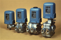
The Foxboro model 13A pneumatic d/p cell transmitters measure differential pressure and transmit a proportional pneumatic output signal.


The information above is attributed to Tony Kuphaldt and is licensed under the Creative Commons Attribution 3.0.

The Rotary Globe Control Valve

Neles Rotary Control Valve
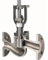
Neles, a division of Metso, offers their "RotaryGlobe" control valve designed to control a wide range of process liquids, gases and vapors. Its provides reliable and rugged construction and is available with a variety of different trim choices.  An excellent candidate for general, difficult and even severe service control valve applications for many industries including chemical, petrochemical, water treatment, pulp and paper, and power generation. The Neles RotaryGlobe valve provides excellent control accuracy with the inherent benefits of a rotary valve. The optimized design results in reliability and control stability and also reduces lifetime costs and maintenance needs.

See the video below for a "look inside".

Closed Loop Control System Basics

closed loop control
Closed loop diagram
The video below explains the concept of a closed loop control system, using a steam heat exchanger and food processing application as an example.

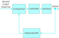
A closed loop control system uses a sensor that feeds current system information back to a controller. That information is then compared to a reference point or desired state. Finally, a a corrective signal is sent to a control element that attempts to make the system achieve its desired state.

A very basic example of a temperature control loop includes a tank filled with product (the process variable), a thermocouple (the sensor), a thermostat (the controller), and a steam control valve feeding a tubing bundle (the final control element).

The video outlines all the major parts of the system, including the measured variable, the set point, the controlled variable, controller, error and disturbance.

Automation Competency Model Helps Guide Future Technical Workforce

Author, Stephen R. Huffman, Vice President, Marketing and Business Development, at Mead O’Brien, Inc.
Eight years ago, the Automation Federation (AF) delegation told an audience at the Employment and Training Administration (ETA) about the people practicing automation careers in industry. Not long before our visit, the ETA, part of the U.S. Department of Labor (DOL), had worked with the National Institute of Standards and Technology (NIST) to develop a “competency model” framework based on the needs of advanced manufacturing. The ETA was eager to engage AF and ISA to use our tiered framework to develop a competency model for the automation profession.

After developing the preliminary model, hosting subject-matter expert (SME) meetings facilitated by the DOL to finalize our work, and then testing the model with several automation managers against their own criteria for validity, we rolled out the Automation Competency Model (ACM) to educators, government, and industry in 2008. Since then, it has been a tool for educators and parents to show students what automation professionals do, management to understand the skill sets their employees need to be effective and to use as a tool for gap analysis in reviews, program developers to create or alter curricula for effective education and training, and lawmakers to understand how U.S. manufacturing can be globally competitive and the jobs needed to reach that goal.

In the lower tiers, the model identifies necessary soft skills, including personal effectiveness, academic, and general workplace competencies. Automation-specific work functions, related competencies, and references (e.g., standards, certifications, and publications) are detailed in tier 5. In short, the model stakes out our professional territory and serves as a benchmark for skill standards for all aspects of process and factory automation. Previously, parts of the academic community and some U.S. lawmakers and agencies had the misconception that industrial automation and information technology (IT) are synonymous. Although there has been some convergence between IT and operational technology (OT), much of that perception has changed. OT-based industrial automation and control systems (IACS) were a focus in the recent cybersecurity framework development organized by NIST in response to the presidential executive order on cybersecurity for critical infrastructure.

The ACM has been a great tool for the AF to use to draw new organizational members and working groups, who visualize the big picture in automation career development. Also, we are telling our story and forming partnerships with science, technology, engineering, and math (STEM) organizations such as FIRST and Project Lead the Way. Since forming in 2006, AF now has 16 members representing more than 500,000 automation-related practitioners globally. After two three-year critical reviews, the ACM is still the most downloaded competency model on the DOL website. As a result of our work in creating the ACM and the IACS focus in cybersecurity framework meetings, the DOL asked AF to review a heavily IT focused Cybersecurity Competency Model. After adding IACS content and the philosophy of plant operation (versus IT) cybersecurity, the model released was a much stronger tool with wider applicability.

Recently, ISA, as a member of the American Association of Engineering Societies (AAES), presented the development of the ACM to AAES leadership as a way to provide tools for lifelong learning in the engineering profession. AF/ISA was once again invited to work with the DOL and other AAES member societies to lead in developing an Engineering Competency Model. The model framework and our experience in ACM development enabled us to identify the front-end skills, necessary abilities, knowledge to be developed, and academic prerequisites for any of the disciplines, plus industry-wide competencies from the perspective of all engineering-related plant functions: design, manufacturing, construction, operations and maintenance, sustainability and environmental impact, engineering economics, quality control and assurance, and environmental health and safety—with emphasis on cyber- and physical security, and plant safety and safety systems.

Now the societies dedicated to each vertical discipline listed in tier 5 will begin to identify all critical work functions, detail all competencies within each function, and note the reference materials. It is important for the participants to see the big picture, consider the future, and keep an open mind; agreement typically comes easily when SMEs participate with that mindset. Once the model through tier 5 is complete, job titles and job descriptions are created. When the DOL accepts the model, the U.S. government officially recognizes these positions. We hope the emerging Engineering Competency Model will be a great tool to address the overall skilled worker shortage. If the automation model is any indication, the new engineering model will have a large impact on achieving the skilled workforce goal.

Welcome to Mead O'Brien's Steam, Valve, Process Control, and HVAC Blog

Welcome and thanks for visiting. We established this blog as a means to provide educational information in the field of steam management, industrial hot water systems, industrial valves, and process instruments.

Our weekly posts will attempt to teach the reader something new and interesting in the field of industrial control and HVAC.

We hope you enjoy our content and please visit back often.