 |
| Pneumatic transmitters (courtesy of Foxboro) |
The indicator in this case would be a special pressure gauge, calibrated to read in units of process pressure although actuated by the pressure of clean compressed air from the transmitter instead of directly by process fluid. The most common range of air pressure for industrial pneumatic instruments is 3 to 15 PSI. An output pressure of 3 PSI represents the low end of the process measurement scale and an output pressure of 15 PSI represents the high end of the measurement scale. Applied to the previous example of a transmitter calibrated to a range of 0 to 250 PSI, a lack of process pressure would result in the transmitter outputting a 3 PSI air signal and full process pressure would result in an air signal of 15 PSI. The face of this special “receiver” gauge would be labeled from 0 to 250 PSI, while the actual mechanism would operate on the 3 to 15 PSI range output by the transmitter. As with the 4-20 mA loop, the end-user need not know how the information gets transmitted from the process to the indicator. The 3-15 PSI signal medium is once again transparent to the operator.
Typically, a 3 PSI pressure value represents 0% of scale, a 15 PSI pressure value represents 100% of scale, and any pressure value in between 3 and 15 PSI represents a commensurate percentage in between 0% and 100%. The following table shows the corresponding current and percentage values for each 25% increment between 0% and 100%. Every instrument technician tasked with maintaining 3-15 PSI pneumatic instruments commits these values to memory, because they are referenced so often:

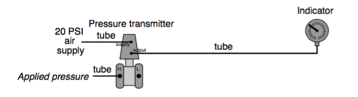
Using the Foxboro model 13A pneumatic differential pressure transmitter as an example, the video below highlights the major design elements of pneumatic transmitters, including an overview of "maximum working pressure" versus "maximum measurement range" pressure.
The Foxboro model 13A pneumatic d/p cell transmitters measure differential pressure and transmit a proportional pneumatic output signal.
The information above is attributed to Tony Kuphaldt and is licensed under the Creative Commons Attribution 3.0.